Inst ToolsInst ToolsInst Tools
  • Courses
  • Automation
    • PLC
    • Control System
    • Safety System
    • Communication
    • Fire & Gas System
  • Instrumentation
    • Design
    • Pressure
    • Temperature
    • Flow
    • Level
    • Vibration
    • Analyzer
    • Control Valve
    • Switch
    • Calibration
    • Erection & Commissioning
  • Interview
    • Instrumentation
    • Electrical
    • Electronics
    • Practical
  • Q&A
    • Instrumentation
    • Control System
    • Electrical
    • Electronics
    • Analog Electronics
    • Digital Electronics
    • Power Electronics
    • Microprocessor
  • Request
Search
  • Books
  • Software
  • Projects
  • Process
  • Tools
  • Basics
  • Formula
  • Power Plant
  • Root Cause Analysis
  • Electrical Basics
  • Animation
  • Standards
  • 4-20 mA Course
  • Siemens PLC Course
Reading: Difference between Invasive, Non-invasive, Intrusive & Non-intrusive
Share
Font ResizerAa
Inst ToolsInst Tools
Font ResizerAa
  • Courses
  • Design
  • PLC
  • Interview
  • Control System
Search
  • Courses
  • Automation
    • PLC
    • Control System
    • Safety System
    • Communication
    • Fire & Gas System
  • Instrumentation
    • Design
    • Pressure
    • Temperature
    • Flow
    • Level
    • Vibration
    • Analyzer
    • Control Valve
    • Switch
    • Calibration
    • Erection & Commissioning
  • Interview
    • Instrumentation
    • Electrical
    • Electronics
    • Practical
  • Q&A
    • Instrumentation
    • Control System
    • Electrical
    • Electronics
    • Analog Electronics
    • Digital Electronics
    • Power Electronics
    • Microprocessor
  • Request
Follow US
All rights reserved. Reproduction in whole or in part without written permission is prohibited.
Inst Tools > Blog > Flow Measurement > Difference between Invasive, Non-invasive, Intrusive & Non-intrusive

Difference between Invasive, Non-invasive, Intrusive & Non-intrusive

Invasive Sensor will be in contact with process flow and the Intrusive Sensor will be mounted on the pipeline but it can be in contact or no contact with flow.

Last updated: November 1, 2023 2:16 pm
Editorial Staff
Flow Measurement
2 Comments
Share
4 Min Read
SHARE

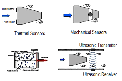
Invasive devices have transducers that come into contact with the flowing fluid. They are also called ‘wetted’ transducers.

Contents
Invasive TypeNon-Invasive TypeIntrusive TypeNon-Intrusive Type

Non–invasive transducers do not come into contact with the fluid and are placed on the outside of the pipe. Intrusive devices protrude into the flow and distort the flow profile, as can be seen in the top two diagrams.

The distortion often leads to mis-measurement by introducing asymmetry to the velocity profile.

Different devices can be intrusive but non-invasive or even invasive but non-intrusive. For example, the ultrasonic meters are both non-intrusive and non-invasive.

The reason non-intrusive and especially non-invasive flow meters are so popular is because they do not protrude into the flow, do not come in contact with fluid, and do not generate any pressure losses.

The below table will give us clarity about Invasive and non-invasive and similarly Intrusive & non-intrusive.

Invasive Type

Sensor will be in contact with the process flow

Non-Invasive Type

Sensor will be mounted externally and there will be NO contact with process flow.

Intrusive Type

Sensor will be placed/mounted in the pipeline but either it can be in-contact or no-contact with the process flow.

Non-Intrusive Type

Sensor will be placed/mounted outside the pipeline but either it can be in-contact or no-contact with the process flow.

Difference between Invasive & Non-invasive and Intrusive & Non-intrusive

Non intrusive devices do not interfere with the flow profile. No pressure drop is observed meaning that these devices are more cost effective to operate. They are also non-invasive which means they do not come into contact with the fluid being measured.

This is very beneficial when measuring dangerous or corrosive fluids that could damage sensor heads. It also means the transducers can be used alongside heavily fouling fluids and not be affected. This extends the life of the transducers, again saving money.

There is no need to break into the pipeline to install these meters which means they can be installed without shutting down the process. This makes them ideal for use on a number of different lines for verification purposes as they are easily portable. There is no chance of leakage or contamination.

The turn down ratio is the range at which a meter can operate within its stated uncertainty levels. It is written as a ratio of the highest flow rate in its range compared to the lowest.

For a more traditional flow meter such as a differential pressure meter or a turbine meter, the turndown ratio is around 10:1. A non-invasive ultrasonic meter however can have a turndown ratio of up to 400:1.

There are no moving parts associated with ultrasonic meters and hence no wear and tear. A turbine meter may have to be maintained in order to achieve peak performance but this is not the case with non-invasive technology.

This low maintenance means it will continue to deliver a consistent reading for as long as transducers are working. And even if they fail then they can be easily replaced with new ones without shutting down the process.

Reference: tuvnel

If you liked this article, then please subscribe to our YouTube Channel for Instrumentation, Electrical, PLC, and SCADA video tutorials.

You can also follow us on Facebook and Twitter to receive daily updates.

Read Next:

  • Inductive Proximity Switch 
  • Transit Time Flow meter
  • Field Transmitter Principle
  • Instrument documents
  • Orifice Turndown ratio
Don't Miss Our Updates
Be the first to get exclusive content straight to your email.
We promise not to spam you. You can unsubscribe at any time.
Invalid email address
You've successfully subscribed !

Continue Reading

Coriolis Mass Flow Sensor Theory
DP type Flow Transmitter Preventive Maintenance and Calibration
Turbine Flow Meter Installation Procedure
What is a Flow Element? – Types, Comparison of Flow Elements
Turbine Flow Meter – Principle, Advantages, Disadvantages
What is a Paddle Wheel Flow Meter?
Share This Article
Facebook Whatsapp Whatsapp LinkedIn Copy Link
Share
2 Comments
  • tushar Parekh says:
    February 10, 2018 at 10:45 am

    simply outstanding

    Reply
  • Shahabuddin says:
    August 14, 2018 at 4:05 pm

    Pliz sir need your help I need interview questions and answers

    Reply

Leave a Reply Cancel reply

Your email address will not be published. Required fields are marked *

Stay Connected

128.3kFollowersLike
69.1kFollowersFollow
210kSubscribersSubscribe
38kFollowersFollow

Categories

Explore More

What are the Orifice Plate Flow Requirements?
What is a Thermal Flow Meter?
Troubleshooting DP type Transmitter Common Problems
Variable Area Flow Meters – Principle, Advantages, Disadvantages
Mass Flow Meters
Standardized Volumetric Flow
What is the Purpose of Orifice Plate Drain Hole and Vent Hole?
Turbine Flow Meters Troubleshooting

Keep Learning

Volumetric Flow Calculations

Volumetric Flow Calculations

Bernoulli's Principle

Bernoulli’s Principle and Equation – Flow Measurement

Orifice plate with vent and drain holes

Basics of Orifice Plates

Custody Transfer Meter Checks

Checklist for Custody Transfer Meters: Mass Flowmeter

Flowmeter Characteristics

Flow Meter Characteristics

Measuring Instruments

Flow Instruments – Selection, Principle & Application

Ultrasonic Flow Meters Working Principle

Ultrasonic Flow Meters Working Principle

Sutro weir flow meter principle

Weirs and Flumes Flow Measurement

Learn More

S7-1200 Hardware Configuration

S7-1200 Hardware Configuration – Siemens PLC Tutorials

O Ring Failure

How O-Ring Failure caused NASA’s shuttle to Blast ?

Explain how this is an example of Ratio Control?

Questions on Ratio Control System

PLC Batch System for 4 Tanks Mixing using CX-Programmer

PLC Batch System for 4 Tanks Mixing using CX-Programmer

What is meant by a SCADA System

Troubleshoot the Status of a PLC Via CPU Indicators

CPU Communication Ports in Siemens PLC

Types of CPU Communication Ports in Siemens PLC

Ultrasonic Flow Meters Working Principle

Ultrasonic Flow Meters Working Principle

Power Electronics Objective Questions

Single Phase Semi-Converters Quiz

Menu

  • About
  • Privacy Policy
  • Copyright

Quick Links

  • Learn PLC
  • Helping Hand
  • Part Time Job

YouTube Subscribe

Follow US
All rights reserved. Reproduction in whole or in part without written permission is prohibited.
Welcome Back!

Sign in to your account

Username or Email Address
Password

Lost your password?