Major Difference between Pneumatic, Electrical & Hydraulic Actuators. Read about Pneumatic Actuators, Electrical Actuators & Hydraulic Actuators.
Pneumatic Actuators
A pneumatic control valve actuator converts energy (typically in the form of compressed air) into mechanical motion. The motion can be rotary or linear, depending on the type of actuator.
Pros of Pneumatic Actuators
- Explosion proofing relatively simple
- Relatively insensitive to corroding environments if control air is used
- Unsophisticated design
- Use of control gas possible
- Logic interlocking of signals can be realized easily Relatively low cost
- High stroking velocities can be realized
- “Fail safe outages of the auxiliary energy do not prevent reaching of safe position (spring loaded actuator)”
Cons of Pneumatic Actuators
- Distance to the source of energy is limited (dead time problems)
- Actuating force of spring loaded units is limited
- Auxiliary energy must be generated and made available (cost implications)
- Auxiliary energy system requires considerable maintenance
- Small systems are normally not economical
- Sensitive to changing process pressure
Electrical Actuators
An electric actuator is powered by a motor that converts electrical energy into mechanical torque. The electrical energy is used to actuate equipment such as multi-turn valves.
Additionally, a brake is typically installed above the motor to prevent the media from opening valve. If no brake is installed, the actuator will uncover the opened valve and rotate it back to its closed position. If this continues to happen, the motor and actuator will eventually become damaged. It is one of the cleanest and most readily available forms of actuator because it does not directly involve oil or other fossil fuels.
Pros of Electrical Actuators
- Large distance to the source of energy is no problem
- Accessories and parts are standard supplies Easy interlocking of signals
- High regulation and control accuracy can be realized easily
- Large actuating force easy to achieve
- Remote control and monitoring functions can be implemented easily
Cons of Electrical Actuators
- Larger actuating forces difficult to achieve
- Limited stroking velocity
- Explosion proofing costlier in comparison to pneumatic or hydraulic actuators
- “Reaching of safe position in case of auxiliary energy outages must be ensured
- by additional measures”
- High maintenance costs
Hydraulic Actuators
A hydraulic actuator consists of cylinder or fluid motor that uses hydraulic power to facilitate mechanical operation. The mechanical motion gives an output in terms of linear, rotatory or oscillatory motion. As liquids are nearly impossible to compress, a hydraulic actuator can exert a large force.
The drawback of this approach is its limited acceleration. The hydraulic cylinder consists of a hollow cylindrical tube along which a piston can slide. The term single acting is used when the fluid pressure is applied to just one side of the piston.
The piston can move in only one direction, a spring being frequently used to give the piston a return stroke. The term double acting is used when pressure is applied on each side of the piston; any difference in pressure between the two sides of the piston moves the piston to one side or the other.
Pros of Hydraulic Actuators
- High actuating forces
- High stroking velocities are possible
- Outages of the auxiliary energy do not prevent reaching of safe position (accumulator)
- High stability
Cons of Hydraulic Actuators
- Distance to the source of energy is limited
- Tubing is required for transmission of the actuating power, implying additional leakage risks
- Costly control
- Considerable maintenance requirements
Difference between Pneumatic, Electrical & Hydraulic Actuators

Short Notes on Pneumatic, Electrical & Hydraulic Actuators
Manual actuators for control valves
Manual actuators are useful where the flow through the valve must be very precisely, but no auxiliary energy supply is provided or automatic control is not required.
The closure element is moved by means of a trapezoidal threaded spindle, generally using a hand wheel. Larger actuating forces necessitate graduated transmission by means of gearing.
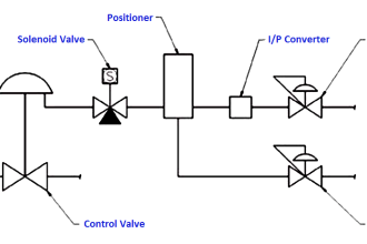
Pneumatic diaphragm actuators
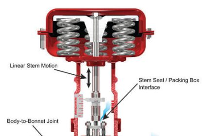
Pneumatically operated diaphragm actuators are using low pressure air supply from controller, positioner or other source. The frictional forces and thus the hysteresis are negligibly low. Molded diaphragms are used to provide linear characteristic and high travels.
An important benefit of the spring diaphragm actuators is their ability to “fail safe” (to close or open the valve on air or signal failure). The fail safe direction depends on the safety requirements. If the fail in place mode is desired spring-diaphragm or other pneumatic actuators have to use block up valves.
Usually there is a central spring design or a multi spring design. Direct acting function is given when increasing air pressure extends actuator stem. When the function is reverse acting increasing air pressure retracts actuator stem.
1. Pneumatic piston actuators
Pneumatically operated piston actuators are using high pressure plant air, often eliminating the need for supply pressure regulator. When the pressure of the supply air is high enough, the actuator forces are higher than with diaphragm actuators. Springless double acting designs give maximum force in both directions.
The friction of piston actuators is higher than of diaphragm actuators. It probably will increase with use because of O-ring and guide surface wear. Maintenance is required more often for this type of actuators.
2. Pneumatic rotary actuators
Rotary actuators are used to operate valves with rotary closure members such as rotary plug valves, ball valves, plug valves or butterfly valves.
3. Diaphragm actuators
With rolling diaphragm good for high strokes Fail safe with spring Usually used for control service
4. Rock and pinion actuator
Recommended for on/off applications because of the backlash
5. Scotch yoke type actuator
The force varies through the stroke
Electrical operated actuators
Control valves with electrical linear or rotary actuators are used when the auxiliary energy is electrical power.
The electric actuators are more complex and more expensive than pneumatic actuators. They offer advantages where no air supply source is available, where low ambient temperatures could freeze condensed water in pneumatic supply lines or where unusually large stem forces are needed.
The electrically operated actuators have an handwheel for manual operation as standard fittings. When the valve must remain in the last travel position (fail-in-place mode) the standard electric gear type actuators are ideal. Normally the actuator is equipped with an electronic positioner, and a position feedback device.
For fail-safe action a standby power source, such as a relay switch actuated battery pack, is necessary. A disadvantage is the must of periodic maintenance and recharging of the battery.
1. Electrical linear motion actuator
The linear actuators are mainly designed for operating control or shut-off valves with a linear stroke and operating forces up to 25 kN. The actuators are adjustable to the required valve stroke and force.
Optional accessories are additional limit switches, position feedback, positioner and a heating resistor.
2. Electric rotary actuator
The electric rotary actuators is composed of a motorised gear train and screw assembly which drives the valve stem. The actuator is equipped with an electronic positioner, and a position feedback device.
Control valves with thrust units and electric multi-turn actuators are generally implemented in centralised heating plants and power stations.
Electro-hydraulic actuators
Electro-hydraulic actuators require electrical power to the motor and an electrical input signal from the controller. This actuators are ideal for isolated location where pneumatic supply pressure is not available but where precise control of valve plug position is needed. They offer the advantage that they can be placed remotely from an instrument.
They are expensive in relation to a pneumatic diaphragm actuated valve. The essence of the design requires a constant source of pressure, which means a constant use of electric power to pump the hydraulic power fluid.
High performance actuators are working with very high pressure. These actuators normally require a external hydraulic source. This hydraulic source can be used for a number of actuators.