Inst ToolsInst ToolsInst Tools
  • Courses
  • Automation
    • PLC
    • Control System
    • Safety System
    • Communication
    • Fire & Gas System
  • Instrumentation
    • Design
    • Pressure
    • Temperature
    • Flow
    • Level
    • Vibration
    • Analyzer
    • Control Valve
    • Switch
    • Calibration
    • Erection & Commissioning
  • Interview
    • Instrumentation
    • Electrical
    • Electronics
    • Practical
  • Q&A
    • Instrumentation
    • Control System
    • Electrical
    • Electronics
    • Analog Electronics
    • Digital Electronics
    • Power Electronics
    • Microprocessor
Search
  • Books
  • Software
  • Projects
  • Process
  • Tools
  • Basics
  • Formula
  • Power Plant
  • Root Cause Analysis
  • Electrical Basics
  • Animation
  • Standards
  • 4-20 mA Course
  • Siemens PLC Course
Reading: Difference Between Open Circuit and Close Circuit
Share
Notification Show More
Font ResizerAa
Inst ToolsInst Tools
Font ResizerAa
  • Courses
  • Design
  • PLC
  • Interview
  • Control System
Search
  • Courses
  • Automation
    • PLC
    • Control System
    • Safety System
    • Communication
    • Fire & Gas System
  • Instrumentation
    • Design
    • Pressure
    • Temperature
    • Flow
    • Level
    • Vibration
    • Analyzer
    • Control Valve
    • Switch
    • Calibration
    • Erection & Commissioning
  • Interview
    • Instrumentation
    • Electrical
    • Electronics
    • Practical
  • Q&A
    • Instrumentation
    • Control System
    • Electrical
    • Electronics
    • Analog Electronics
    • Digital Electronics
    • Power Electronics
    • Microprocessor
Follow US
All rights reserved. Reproduction in whole or in part without written permission is prohibited.
Inst Tools > Blog > Electrical Basics > Difference Between Open Circuit and Close Circuit

Difference Between Open Circuit and Close Circuit

In this post, we will understand the difference between open circuit and short circuit in electrical systems.

Last updated: September 28, 2022 3:44 pm
Viral Nagda
Electrical Basics
No Comments
Share
6 Min Read
SHARE

In this post, we will understand the difference between open circuit and short circuit in electrical systems.

Contents
What is an Open Circuit?What is a Short Circuit?Difference between Open Circuit and Short Circuit

In an electrical system, there are two types of circuits that are related to the flow of current – an open circuit and a short circuit.

Many of us are familiar with these terms, but let us have a look at the difference between both of them. In this post, we will see the difference between an open circuit and a short circuit.

Difference Between Open Circuit and Close Circuit

What is an Open Circuit?

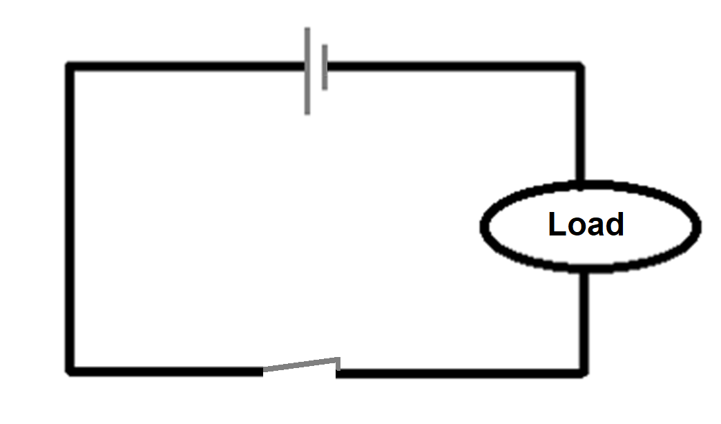
As the name implies, an open circuit means that the circuit is open and no current is flowing through it. Current always requires a path to flow; but when there is no path, then it is open.

Refer to the below figure. As you can see, there is a switch, battery, and load. When the switch is open, no current can flow through the load. This means the two terminals are disconnected and there will be no continuity.

What is an Open Circuit

Now, according to Ohm’s law, R=V/I. As the current is zero, resistance will be infinite.

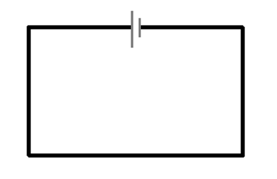
Hence, in an open circuit, the current will be zero; some voltage drop will be present and resistance will be infinite. That is why, in the second image (above), it is depicted that an open circuit is equivalent to zero resistance.

What is a Short Circuit?

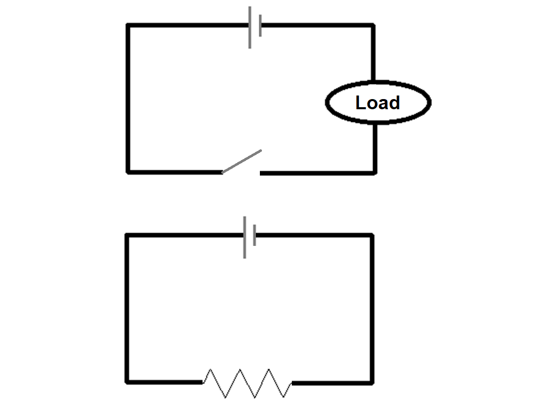
As the name implies, a short circuit means that the circuit is short and a current is flowing through it. Current always requires a path to flow; and when there is a path, then it is short.

Refer to the below figure. As you can see, there is a switch and battery. When the switch is closed, the current can flow through the path. This means the two terminals are connected and there will be continuity.

Now, according to Ohm’s law, R=V/I. As the current is at its maximum value, resistance will be zero. Hence, in a short circuit, the current will be high; voltage drop will be zero and resistance will be zero.

That is why, in the second image, it is depicted that a short circuit is equivalent to zero resistance. A simple wire connected to the battery terminals directly is the best example of a short circuit; because a wire has negligible resistance.

What is an Short Circuit

Now, a short circuit also has a different term as a closed circuit. Basically, as the name implies, a closed circuit allows the current to flow as opposed to an open circuit. But, there will be some resistance in the path due to the load connected.

So, in a closed circuit, there will be some resistance and a nominal amount of current and voltage in the path. All the normal loads that we use when it is on, comes under a closed circuit. Refer to the below image for understanding.

Short and Open Circuit

Difference between Open Circuit and Short Circuit

The below points shows the difference between the open circuit and short circuit.

  • In a normal condition, an open circuit happens when the wire or some sort of contact breaks, which disallows the current to flow. But, a short circuit in a normal condition happens when two wires accidentally touch each other which should not. This will touch the two different potentials with each other and damage the circuit.
  • The current flowing through an open circuit is zero, while the current flowing in the short circuit is infinite.
  • An open circuit has infinite resistance, while a short circuit has zero resistance.
  • The voltage in an open circuit is nearly equal to zero, whereas, in a short circuit, it is infinite.
  • In an electrical circuit, an open circuit is denoted by ( ); whereas a short circuit is denoted by ( . ).
  • An open circuit is not harmful to an electrical circuit; it will just break the path. But, a short circuit is harmful to an electrical circuit; as a very large amount of current flows and it can damage the path.
  • An ideal ammeter can be considered a short circuit, as it has zero resistance. An ideal voltmeter can be considered as an open circuit due to large or infinite resistance.

In this way, we saw the difference between an open circuit and a short circuit.

If you liked this article, then please subscribe to our YouTube Channel for Instrumentation, Electrical, PLC, and SCADA video tutorials.

You can also follow us on Facebook and Twitter to receive daily updates.

Read Next:

  • Electrical Substation
  • Automatic Transfer Switch
  • Partial Discharge in Power Lines
  • Routine Tests of Circuit Breakers
  • Dahlander Motor Control Circuit
Don't Miss Our Updates
Be the first to get exclusive content straight to your email.
We promise not to spam you. You can unsubscribe at any time.
Invalid email address
You've successfully subscribed !

Continue Reading

What is Variable Air Volume Controller in HVAC?
How does an Electric Motor Operate? – AC Motor Fundamentals
What is a Link Box?
What are DOL and RDOL starters? Advantages, Disadvantages
What is Vacuum Circuit Breaker?
What is Power Cable? Types of Power Cables
Share This Article
Facebook Whatsapp Whatsapp LinkedIn Copy Link
Share
Leave a Comment

Leave a Reply Cancel reply

Your email address will not be published. Required fields are marked *

Stay Connected

128.3kFollowersLike
69.1kFollowersFollow
208kSubscribersSubscribe
38kFollowersFollow

Categories

Explore More

Types of Motor Enclosures
Download Electrical Enclosure Book
What is a Lightning Arrester? How does it work?
One Nation One Grid One Frequency – Electrical Engineering
What is Automatic Circuit Recloser? Principle and Types
What is an Armoured Cable? Classification of Cables
What is an Auto Changeover Switch?
What are HP and LP Switches in HVAC?

Keep Learning

Automatic Motor Forward and Reverse Control using Timer

Automatic Motor Forward and Reverse Control using Timer

Difference Between Circuit Breaker and Disconnector

Difference Between Circuit Breaker and Disconnector

What is an HRC Fuse

What is an HRC Fuse? – Material, Types, Advantages

running two single-phase induction motors sequentially

Control Two Motors in Sequence after Time Delay – Circuit, Operation

Difference Between Circuit Breaker and Fuse

Difference Between Circuit Breaker and Fuse

Simplified Induction Motor - Cross Section

Siemens Standard Drives Application Handbook (PDF)

Lightning Arrester Basics and Terminology

Lightning Arrester Basics and Terminology

How to Test a Motor using Megger

How to Test a Motor using Megger?

Learn More

Two Hand Control Logic

Two Hand Control Logic using PLC

LIC and FIC Controllers

What LIC and FIC Controllers will do?

radar-level-sensor-

Non-Contacting Radar Level Transmitter Working Principle

Thermocouple Software compensation

Thermocouple Software compensation

Siemens PLC-to-PLC Communication Project

GET Command – Siemens PLC-to-PLC Communication Project

WHILE DO Statement in SCL Language

WHILE DO Statement in SCL Language

PLC Program using Timers

PLC Timers Program

Cobot - Collaborative Robot

What is Cobot? – Collaborative Robot

Follow US
All rights reserved. Reproduction in whole or in part without written permission is prohibited.
Welcome Back!

Sign in to your account

Username or Email Address
Password

Lost your password?