Difference Between 2 wire RTD, 3 wire RTD, and 4 wire RTD’s
RTDs (Resistance Temperature Detectors) are offered with 2, 3, or 4 lead configuration. The best configuration for a specific application depends on a number of factors, however the sensor configuration must match with Transmitter, otherwise leadwire resistance cancellation circuitry may be ineffective.
Also Read: Introduction to RTD’s
Factors to consider:
- Cost of installation – more wires generally means higher cost
- Available space – more or larger wires require more space
- Accuracy requirements – 2 wire configurations may provide the required accuracy, especially with high resistance elements
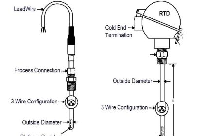
Types of RTD Constructions:
- 2 Lead Construction
- 3 Lead Construction
- 4 Lead Construction
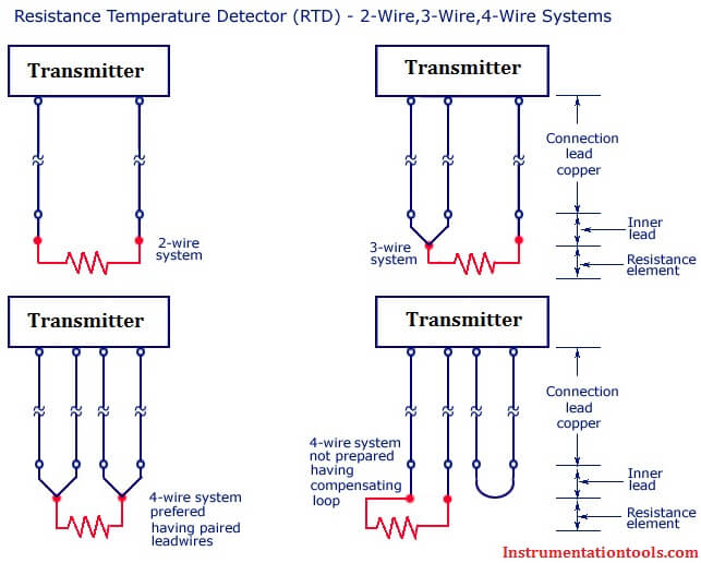
RTD Wiring Diagram
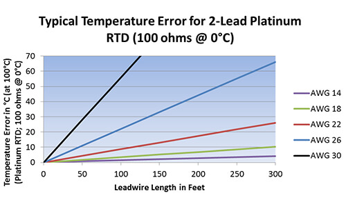
2-lead constructions result in leadwire resistance getting added to the element resistance. Consequently, the temperature reading is artificially high. The graph below shows the temperature error, from 2 leads of various sizes and lengths, for a 100-ohm platinum RTD at 100°C.

2-wire construction is the least accurate of the 3 types since there is no way of eliminating the lead wire resistance from the sensor measurement. 2-wire RTD’s are mostly used with short lead wires or where close accuracy is not required.
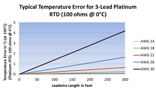
3-lead constructions result in canceled leadwire resistance error only if the transmitter can measure true 3-wire resistance.
- Leadwire resistance error cancelation is most effective when all the lead wires have the same resistance. Using 3 wires of the same AWG, length, and composition will typically result in leadwire resistances matched within 5%. The graph below shows the temperature error from leadwire of various sizes and lengths, for a 3-lead 100-ohm platinum RTD at 100°C.
3-wire construction is most commonly used in industrial applications where the third wire provides a method for removing the average lead wire resistance from the sensor measurement. When long distances exist between the sensor and measurement/control instrument, significant savings can be made in using a threewire cable instead of a four-wire cable
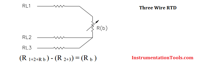
The 3 wire circuit works by measuring the resistance between #1 & #2 (R 1+2) and subtracting the resistance between #2 & #3 (R 2+3) which leaves just the resistance of the RTD bulb (R b). This method assumes that wires 1,2 & 3 are all the same resistance
4-lead constructions result in canceled resistance only if the transmitter can measure true 4-wire resistance. True 4-wire resistance measurement will effectively cancel leadwire resistance error even if all 4 wires are not the same AWG, length, and/or composition.
4-wire construction is used primarily in the laboratory where close accuracy is required. In a 4 wire RTD the actual resistance of the lead wires can be determined and removed from the sensor measurement.
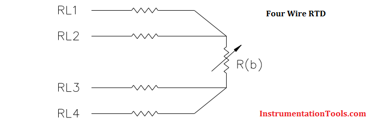
The 4-wire circuit is a true 4-wire bridge, which works by using wires 1 & 4 to power the circuit and wires 2 & 3 to read. This true bridge method will compensate for any differences in lead wire resistances.
Are any configurations interchangeable?
- 4-lead RTDs can generally be used as 3-lead RTDs by eliminating (or tying off) one of the leads
- 4-lead RTDs can be used as 2-lead RTDs, by combining (shorting) the common leads (usually of like color – white/white and red/red)
WARNING: combining the common leads eliminates leadwire resistance cancellation benefits - 3-lead RTDs can be used as 2-lead RTDs, by combining (shorting) the common leads ((usually of like color)
WARNING: combining the common leads eliminates leadwire resistance cancellation benefits
Also Read: Difference Between RTD, Thermocouple & Thermistor


I have learnt a lot