Inst ToolsInst ToolsInst Tools
  • Courses
  • Automation
    • PLC
    • Control System
    • Safety System
    • Communication
    • Fire & Gas System
  • Instrumentation
    • Design
    • Pressure
    • Temperature
    • Flow
    • Level
    • Vibration
    • Analyzer
    • Control Valve
    • Switch
    • Calibration
    • Erection & Commissioning
  • Interview
    • Instrumentation
    • Electrical
    • Electronics
    • Practical
  • Q&A
    • Instrumentation
    • Control System
    • Electrical
    • Electronics
    • Analog Electronics
    • Digital Electronics
    • Power Electronics
    • Microprocessor
  • Request
Search
  • Books
  • Software
  • Projects
  • Process
  • Tools
  • Basics
  • Formula
  • Power Plant
  • Root Cause Analysis
  • Electrical Basics
  • Animation
  • Standards
  • 4-20 mA Course
  • Siemens PLC Course
Reading: Determine the Instrument Calibration Error
Share
Font ResizerAa
Inst ToolsInst Tools
Font ResizerAa
  • Courses
  • Design
  • PLC
  • Interview
  • Control System
Search
  • Courses
  • Automation
    • PLC
    • Control System
    • Safety System
    • Communication
    • Fire & Gas System
  • Instrumentation
    • Design
    • Pressure
    • Temperature
    • Flow
    • Level
    • Vibration
    • Analyzer
    • Control Valve
    • Switch
    • Calibration
    • Erection & Commissioning
  • Interview
    • Instrumentation
    • Electrical
    • Electronics
    • Practical
  • Q&A
    • Instrumentation
    • Control System
    • Electrical
    • Electronics
    • Analog Electronics
    • Digital Electronics
    • Power Electronics
    • Microprocessor
  • Request
Follow US
All rights reserved. Reproduction in whole or in part without written permission is prohibited.
Inst Tools > Blog > Practical Questions > Determine the Instrument Calibration Error

Determine the Instrument Calibration Error

Determine what kind of calibration error the instrument has (zero shift, span shift, hysteresis, and/or linearity).

Last updated: August 13, 2020 8:48 pm
Editorial Staff
Practical Questions
No Comments
Share
2 Min Read
SHARE

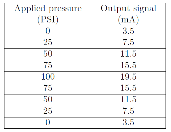
Suppose an electronic pressure transmitter has an input range of 0 to 100 PSI and an output range of 4 to 20 mA. When subjected to a 5-step up-and-down “As-Found” calibration test, it responds as such:

Transmitter input range of 0 to 100 PSI

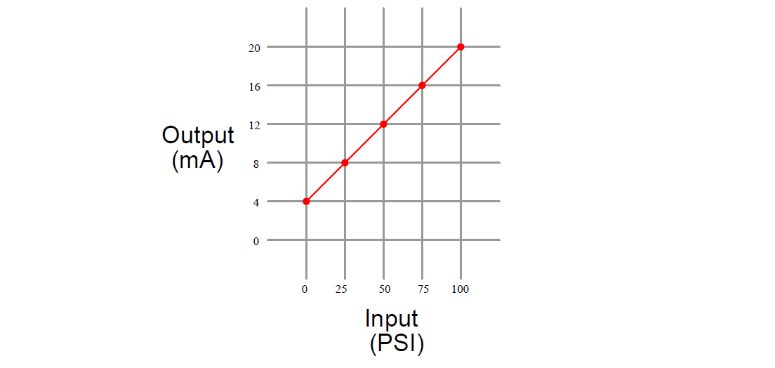
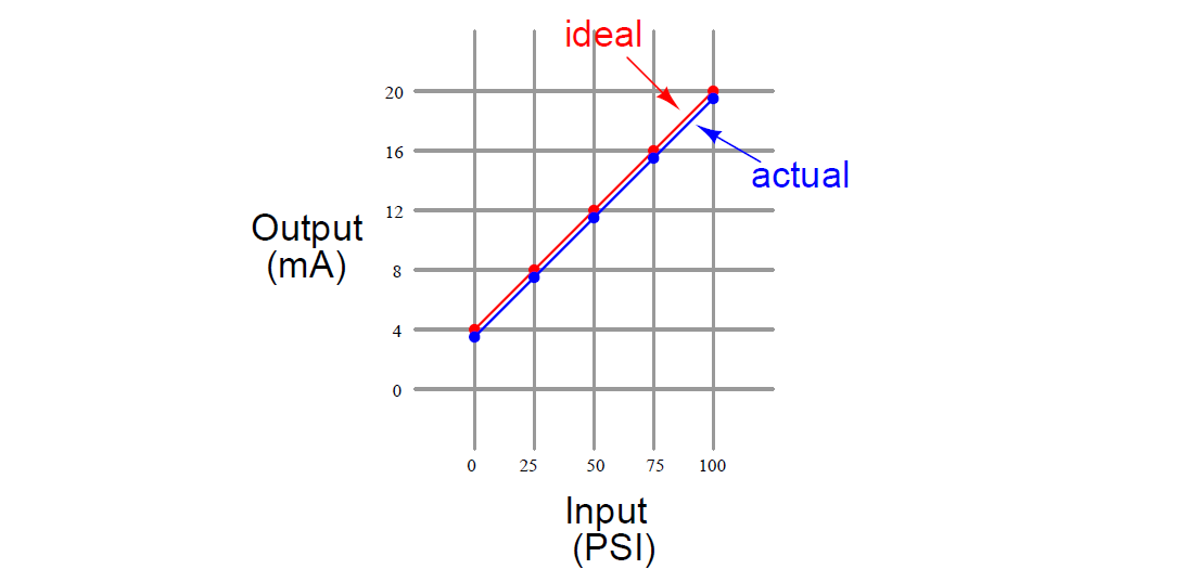
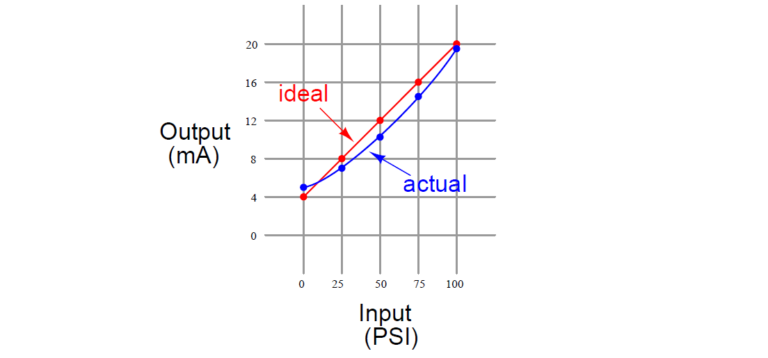
Sketch this instrument’s ideal transfer function on the graph below, along with its actual transfer function graph based on the measured values recorded above. Then, determine what kind of calibration error it has (zero shift, span shift, hysteresis, and/or linearity):

Finally, identify how this calibration error might be corrected. What steps or procedures would you follow to rectify this problem?

How might the other three calibration errors appear when graphed?

What purpose is served by doing an up-and-down test? Why not just check the instrument’s response in one direction only?

Which constant in the y = mx + b linear equation represents zero, and which represents span?

Answer:

This instrument has a zero shift error, but not a span shift or linearity error.

Ideal transfer function:

Ideal transfer function of Transmitter

Actual transfer function: (zero error)

Actual transfer function (zero error)

A span error would look something like this (wrong slope):

A span error with wrong slope

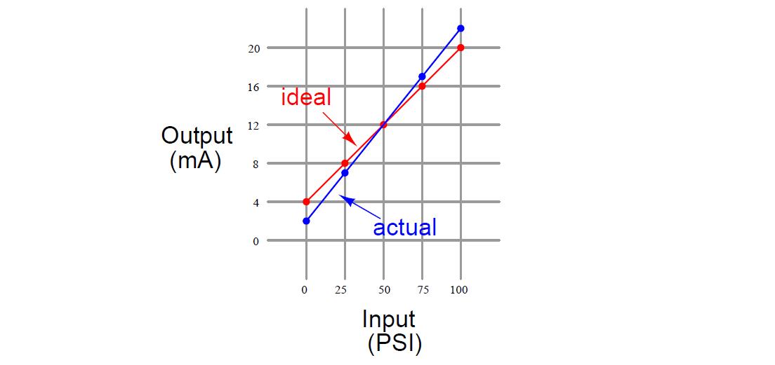
A linearity error would look something like this (not a straight line):

A linearity error

A zero error is usually correctable by simply adjusting the “zero” screw on an analog instrument, without making any other adjustments.

Span errors, by contrast, usually require multiple adjustments of the “zero” and “span” screws while alternately applying 0% and 100% input range values to check for correspondence at both ends of the linear function.

Share your answers with us through below comments section.

Read Next:

  • Bourdon Tube Gauge
  • Instrument Errors
  • Field Instruments
  • Hysteresis
  • Instrument MCQ

Credits: Tony R. Kuphaldt

Don't Miss Our Updates
Be the first to get exclusive content straight to your email.
We promise not to spam you. You can unsubscribe at any time.
Invalid email address
You've successfully subscribed !

Continue Reading

Questions on Pressure Transmitter Calibration Setup
Electric-driven Air Compressor Troubleshooting
Baffle Nozzle Question
How Do You Connect the Differential Pressure Gauge at the Filter?
Tank uses 3 Pressure Transmitters to Measure Level & Density
What is the Purpose of Chemical Seals Pressure Transmitter?
Share This Article
Facebook Whatsapp Whatsapp LinkedIn Copy Link
Share
Leave a Comment

Leave a Reply Cancel reply

Your email address will not be published. Required fields are marked *

Stay Connected

128.3kFollowersLike
69.1kFollowersFollow
210kSubscribersSubscribe
38kFollowersFollow

Categories

Explore More

Hydrostatic Level Transmitter Questions
Liquid Level Switch Control Logic
Programmable Logic Controller (PLC) Questions and Answers – 13
Draw the appropriate Pressure Switch Symbol ?
Something is Wrong with Strain Gauge Bridge Circuit
Calculate Hydraulic System Fluid Pressure
Explain Operation of the Lamp Circuit ?
Identify High and Low Ports on Pneumatic DP Transmitter

Keep Learning

Level Loop Troubleshooting

Identify Faults in PID Control Loop

Ladder Diagram circuit

PLC Practice Questions

DP transmitter Elevated 10 Feet above the Vessel

DP transmitter Elevated 10 Feet above the Vessel

Calculate the Thermocouple’s Measurement Junction Temperature

Calculate the Thermocouple’s Measurement Junction Temperature

pressure switch control two lamps wiring

Draw Wiring of a Pressure Switch to control two lamps

water filter level control system

Practical Process Control System Questions & Answers – 6

Guided-wave Radar Asset Management Parameters

Guided-wave Radar Asset Management Parameters

Two solenoid valves circuit

Solenoid Valves Questions & Answers – 4

Learn More

thermocouple types

What is a Thermocouple ?

Pneumatic Counter for Counting the Strokes of a Cylinder

Pneumatic Counter for Counting the Strokes of a Cylinder

PLC Program Paint Spraying

PLC Program for Paint Spraying

Voltage Regulator Circuit

Basics of Voltage Regulator

PLC Program for fan control unit system

PLC Programming for Fan Control Unit System for Industry

thermocouple voltages

Manually Interpreting Thermocouple Voltages

Multiple Thermowell Installations Problems

Multiple Thermowell Installations Problems

Power Electronics Objective Questions

Power Electronics Applications Objective Questions

Menu

  • About
  • Privacy Policy
  • Copyright

Quick Links

  • Learn PLC
  • Helping Hand
  • Part Time Job

YouTube Subscribe

Follow US
All rights reserved. Reproduction in whole or in part without written permission is prohibited.
Welcome Back!

Sign in to your account

Username or Email Address
Password

Lost your password?