In each industrial process plant, there are many electrical motors of different sizes (and types) that are used for different process functions. Control and signal interfacings of such motors shall be designed and implemented by collaboration of different technical Teams in the Detail Design Engineering phase of project (mainly by PROCESS, I&C, and ELECTRICAL Teams). In this article, we will review the typical sequence and activities for designing and Implementing Control of Motors in one Process Plant.
Motor Control
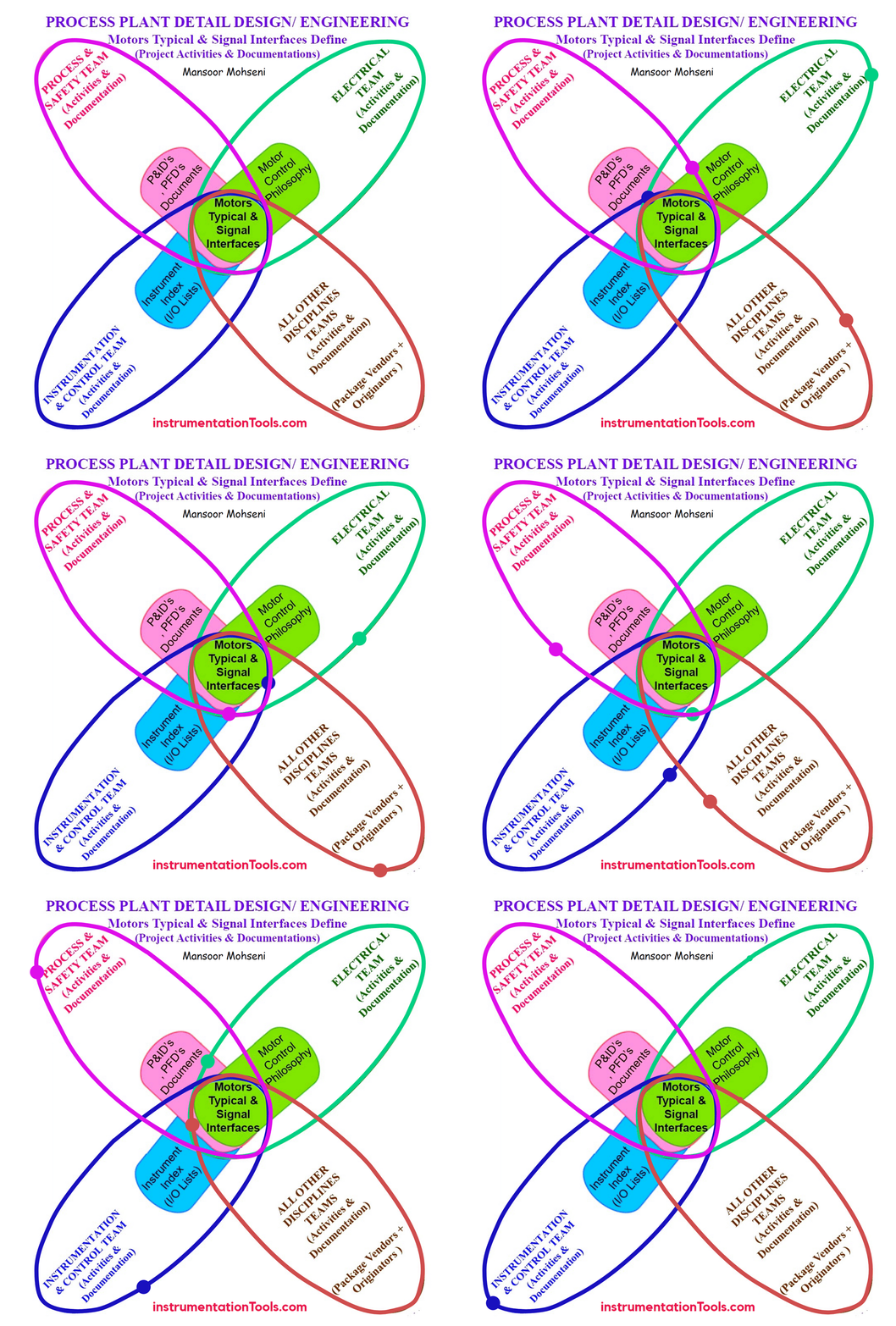
Figure-1: Engagement Model for Motors Typical (Control) & Signal Interfaces Define (In Process Plant Detail Design/ Engineering Phase of Project).
Defining Motors Typical Control & Signal Interface
For doing the design and implementation of controls (and signal interfacings) on required motors in the process plant project (during Detail Design Engineering), the quantity and type of functionalities and operating modes/ actions of all motors shall be first specified and then classified (based on Process Requirements) by the sequence of activities and documentations.
Figure-1 may illustrate a good engagement model for the coordination of different technical Teams (mainly PROCESS, I&C, and ELECTRICAL Teams) for doing activities and producing relevant documents for the mentioned target.
By considering Figure-1, the sequence of interactions between technical Teams may be generally considered as the Interactions Model shown in Figure-2. We consider this model as the basis of our study for our reviewing of required activities and documentation.
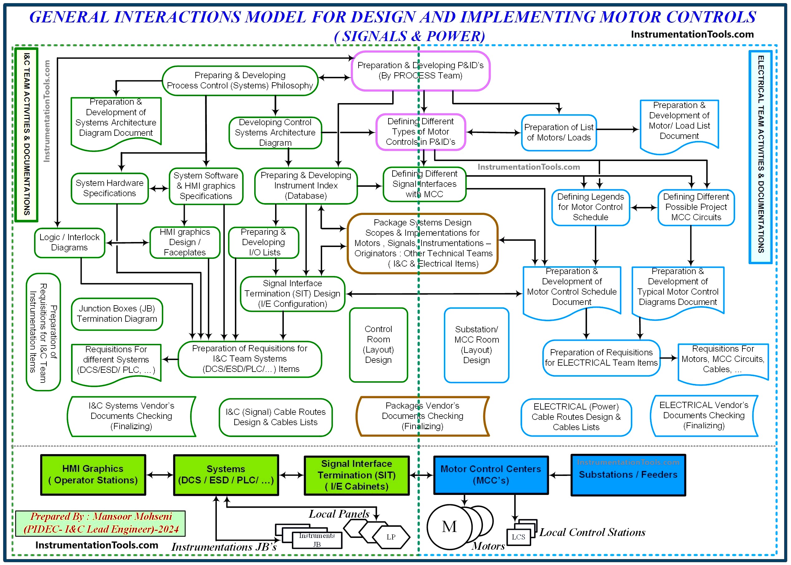
Figure-2: General Interactions Model for Design and Implementing Motor Controls (Sequence of Activities and Documentations)
Defining Typical Motor Controls in P&ID
During the preparation and development of P&ID Documents, all required facilities and functionalities relevant to each motor shall be specified. If such conditions are mentioned in P&IDs for each motor, the documents will be very busy and very complex for tracing and interpreting the process flow of functions. In order to trim the P&ID documents in a suitable way (while preventing missing any required data), usually some templates are defined as Typical Models of possible signal interfacings applicable for motors in the project.
In fact, by defining applicable requirements and functionalities by Process-Team, and by accommodating the Instrumentation and Control (I&C) Team for clarification on applicable signal interfaces (due to considered Process Control Philosophy and possible Control & Safety Systems in the project) all motors in the project are classified to some limited template models.
By providing such templates, then it is possible to classify control of all motors in the project by some limited standard formats (which are easily understandable). Figure-3 shows an example of a realistic project for defining different templates (detail) for controlling motors.
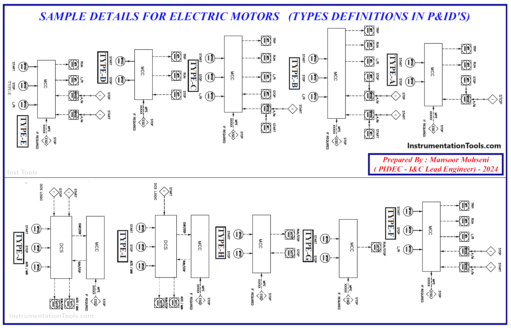
Figure-3: Sample Details for Electric Motors (Types Definition in P&IDs of Realistic Process Plant Project).
After the definition of Type Templates, each motor in P&IDs shall be assigned with suitable type based on required process functionalities. Figure-4 shows some (extraction) examples for assigning such Type Templates for different motors in realistic P&IDs of one Process Plant Project.
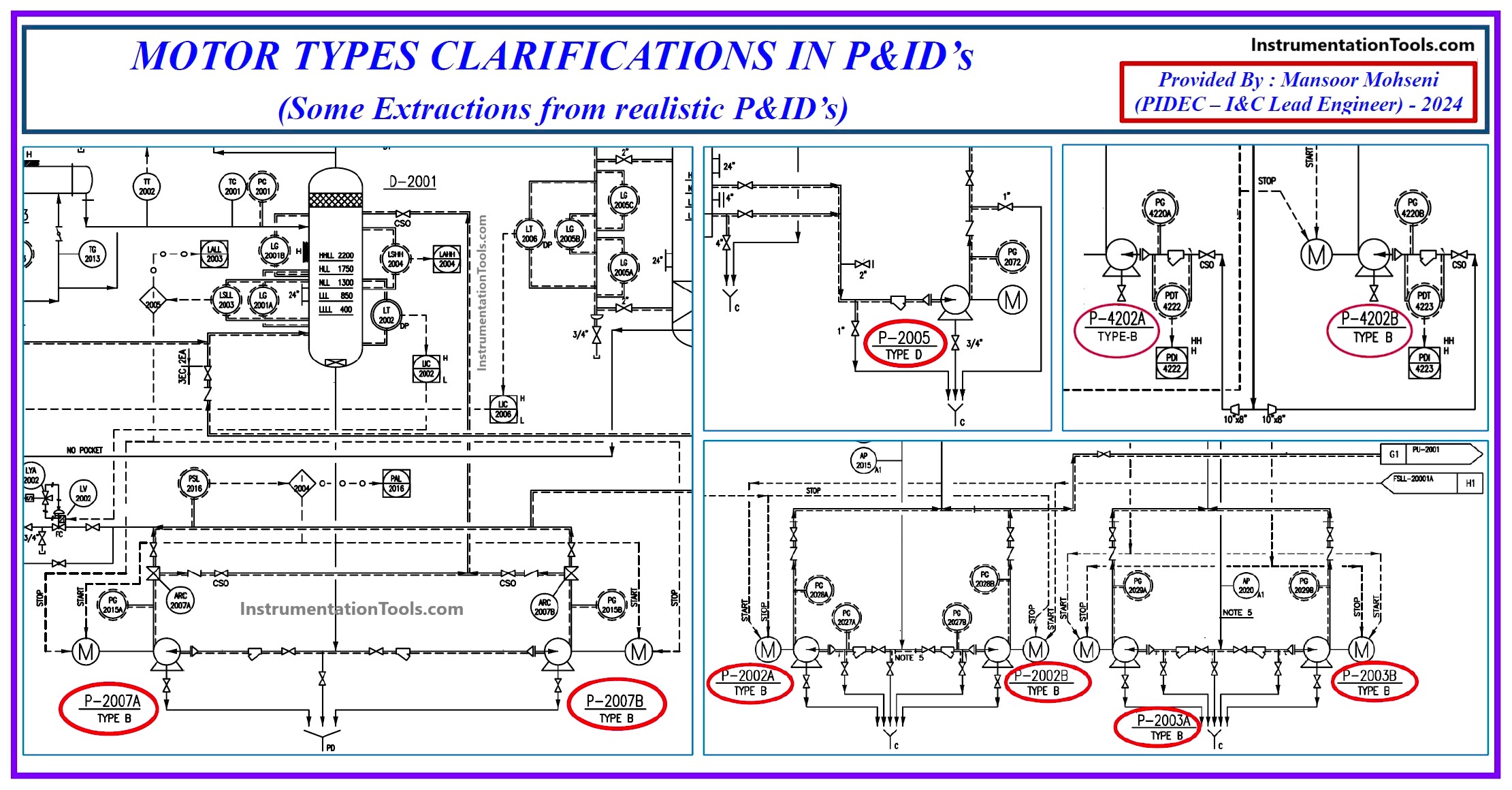
Figure-4: Motor Types Clarifications (Assignment) In P&ID’s (some extractions from realistic P&ID’s of one Process Plant Project).
By reviewing Figures 3 and 4 we can conclude that if during Detail Design Engineering any motors added to the project or required functionality of some motors are changed, then easily relevant required control signals can be defined for such motors by assigning suitable Type Templates to them.
Preparation & Development of Motor/ Load List Document
During the preparation and development of P&ID (and PFD) documents, ELECTRICAL-TEAM (EL) tries to prepare and develop their Motor/ Load List document.
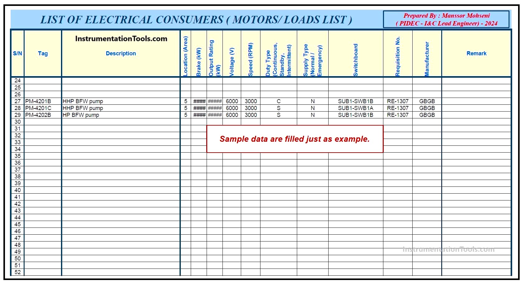
Figure-5: Sample format of “List of Electrical Consumers (Motors/ Loads List)” document.
Figure-5 shows one sample format of the “List of Electrical Consumers (Motors/ Loads List)” document. As it is clear from this figure, it includes all Electrical Consumers who existed in the project with relevant specifications (and data).
Of course, during the development of such a document, ELECTRICAL-TEAM shall assign a suitable switchboard (/feeder) to each item (as shown in the Figure-5) based on available power conditions and extra activity calculations/ estimation document as “Load Balance”. Also due to the type of required supply type (Normal/ Emergency), they shall care for exact cares on different available powers and follow for any further considerations or reconfigurations.
However, the Electrical Consumer List is the primary ELECTRICAL-Team document which is used for following activities and documents on considering proper feeders and design and implementations of required hardware (Switchboards, MCC Circuits, Cables …) or any required coordination with project vendors or other company technical Teams.
Preparing & Developing Instrument Index (Database)
During the preparation and development of P&ID documents, the I&C-Team shall develop a Process Control (System) Philosophy and accordingly start to fill all relevant project data in the Instrument Index (or Instrument Schedule) based on suitably defined procedures and tag numbers. Such file will be completed during the project progress and it will be used for all following activities and documentation of I&C-Team.
By some extractions or processing on the Instrument Index file, the I&C-Team shall prepare and develop the Project document “I/O Lists” and define the list of signal interfacings with MCC circuits and also use data for configuration design of Signal Interface Terminal (or Electrical/ Instrument = E/I) cabinets.
Figure-6 shows a sample of the prepared Signal Interface List with MCC. Of course, such a list is prepared by gathering data from P&ID documents and motor-type assignments shown on those documents. Such a list will be used by the I&C-Team for any coordination with the Electrical-Team and checking their relevant documents.
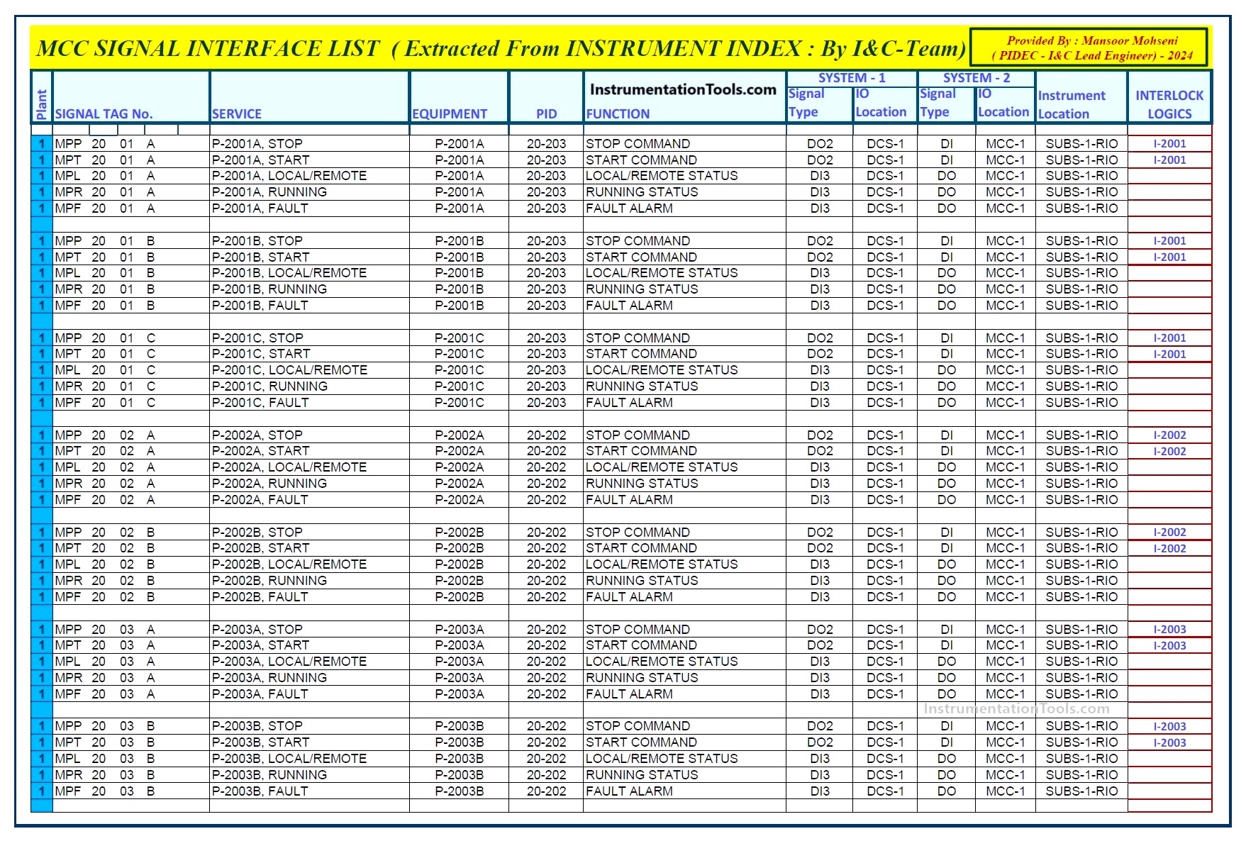
Figure-6: Sample of “List of MCC Signal Interface (which is extracted from Instrument Index file that is in I&C-Team scope).
Such a list shall include Interlock and Analog signal Monitoring Actions on motors too, for considering exact cares on logic Input/ Output signals (may be activated by automatic loops), and segregations and compensation facilities (such as cable screen wire and terminal) for analog signals.
We can find from Figure-6 that suitable Tag numbering definitions may help project progress for standard and quick activities with less probability of faults.
Preparation & Development of Motor Control Schedule Document
The electrical Team based on the control type definition of each motor on P&ID and considering signal interfaces for each control type, will prepare and develop a motor Control Schedule Document. However, for developing such a document they shall define tabular format and available project signal interfaces and then they will fill such table.
Figure-7 shows the sample definition of different Motor Control Type Signals (at the beginning of their document) and then they fill such document shown in Figure-8 (some data are filled as examples).
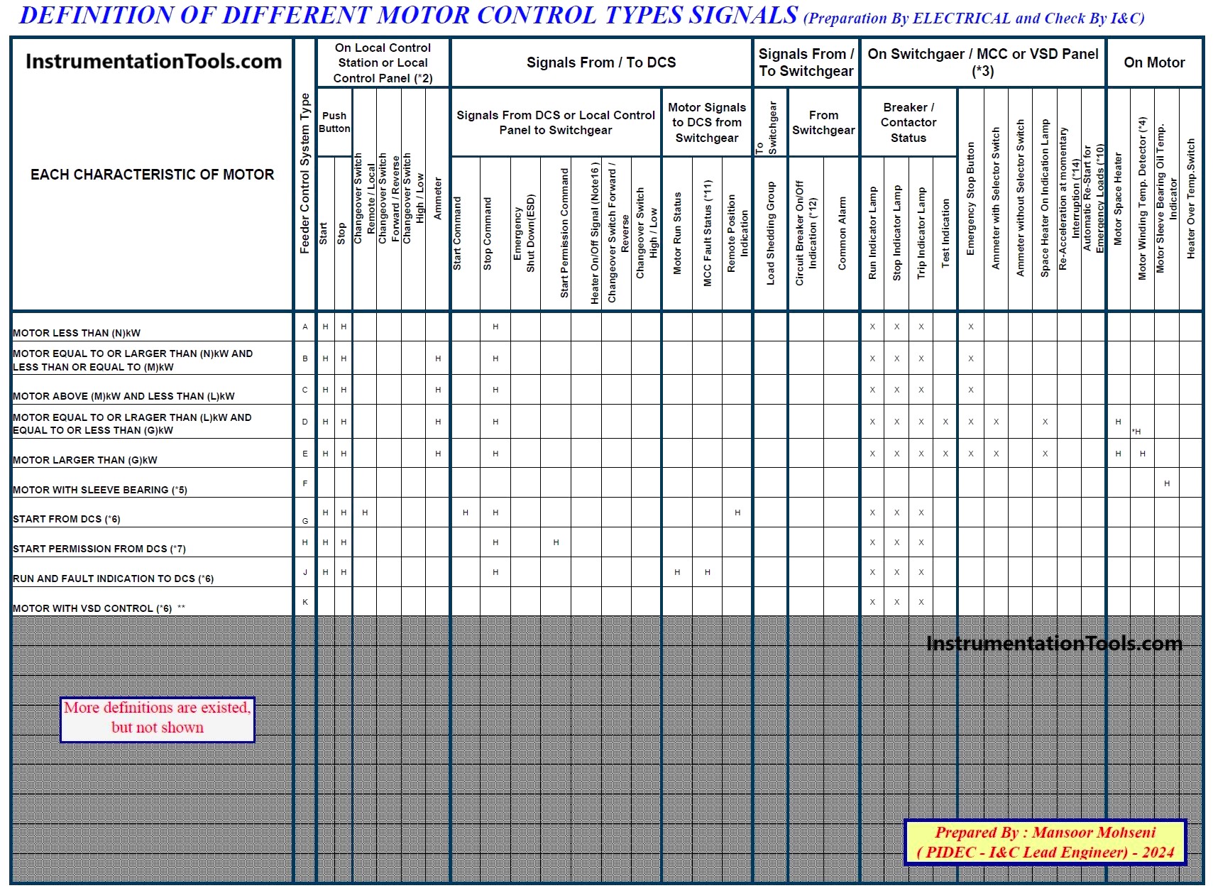
Figure-7: Sample of definition of different Motor Control Type Signals (prepared by EL-Team at the beginning of their document)
The prepared document Motor Control Schedule shall be checked by the I&C-Team based on their provided Motor Signal Interface List during project progress.
During the progress of the detailed design Engineering phase, P&ID documents may have some changes that affect some Motor Control Signal Interfaces, which shall be checked by the I&C-Team and informed EL-Team to develop relevant changes accordingly (Since EL-Team after beginning of the project and during the project progress usually may not refer again to P&ID documents).
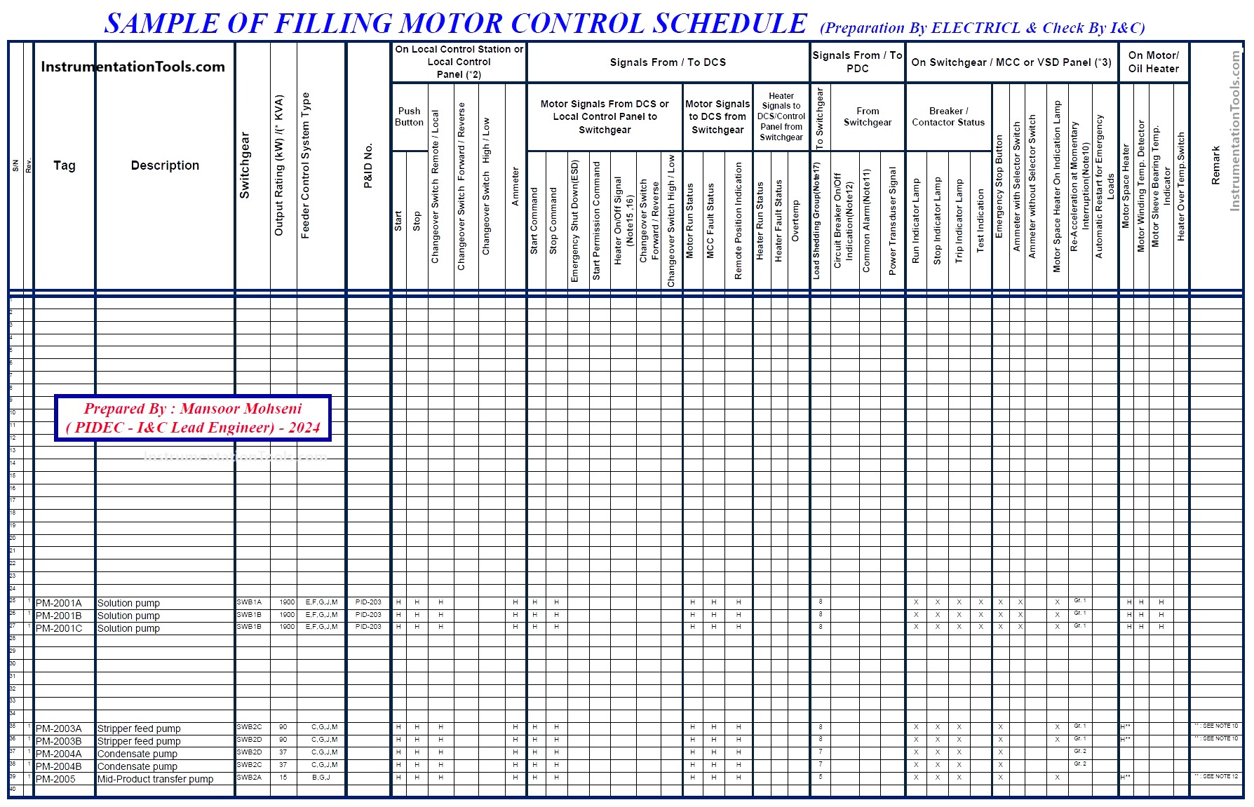
Figure-8: Sample of filling Motor Control Schedule (prepared by EL-Team).
Package Systems Design (Scope & Implementation for Motors)
Each Industrial Process Plant usually has some packages for the realization of some process functionalities or units. Such packages that will have their company originators (maybe other technical teams), may include some motors that shall follow whole project specifications. In order to make uniformity of Motor Control Signal Interfaces and clarify the exact battery limits of implementations (Motor, Cables, Signal Interfaces, MCC …) Company I&C and Electrical Teams shall discuss and negotiate with the package vendors.
Each Package Vendor shall follow the made agreements and reflect them in their documents. Of course, such agreements shall be reflected in I&C and Electrical Teams accordingly (as an example mentioning the package signal interfaces in INSTRUMENT INDEX file by I&C-Team, and consideration of relevant feeders (and probable MCC circuits) in EL-Team documents).
Finalizing each Package Requisition need close coordination and data transfer of Electrical and I&C Teams with other technical teams (especially PROCESS and SAFETY Teams).
Signal Interface Termination Design (I/E Cabinets Configuration)
Due to considering different possible signal interfaces between Process Systems (DCS/ ESD/ PLC) and MCC Circuits, I&C, and Electrical Teams shall discuss and agree on the required hardware configuration based on project conditions and Process Control (System) Philosophy. Such agreements shall be reflected in some company (internal) documents.
Figures 9 and 10 show two Typical MCC Signal Interfaces (agreements between EL and I&C Teams for Hardware Configuration).
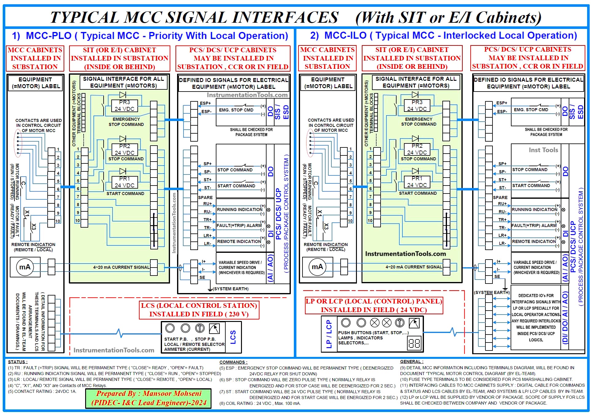
Figure-9: Sample of Typical MCC Signal Interfaces (With SIT or E/I Cabinets).
Figure-9 shows a Typical MCC Signal Interface which is implemented by using SIT or E/I Cabinets in the electrical Substation Location (inside or behind it). As this figure shows, SIT or E/I Cabinets normally include some isolation relays for isolating the MCC Circuit (usually 230 VAC) and the System’s Marshalling Circuits (usually 24 VDC) further to transfer the signals between two points. The terminals in such cabinets (or panels) further to transferring signals have the role of cross-wiring between Systems I/O cables and considered one terminal block for each Motor MCC Connection (see again Figure-9).
On the other hand, the Input Terminals of E/I cabinets are considered for multi-pair cables of different types of Systems I/O’s (for transferring the same digital I/O Types signals), while the output terminals are the form of terminal blocks that gather (or combine) all set of (digital) signals relevant to one Motor. Since the number of Analog signals is usually low quantity, the transfer cable between Systems and E/I Cabinets may be considered as single pair or Multi-pairs, but in any case each signal shall have a screen wire for connection to the system earth for noise reduction (see again the Figure-9).
If the isolation relays (24 VDC) can be transferred inside the MCC Circuits and cross wiring (for gathering or combining Interfacing Signals of one Motor MCC Terminal Block Connection), then easily the E/I Cabinets can be deleted as shown in Figure-10.
In fact, such configuration is very useful if Systems Signals come from Remote I/O cabinets/ panels or Logic Solver (Processor) cabinets that are installed inside the Electrical Substation, based on the Process Control (System) Philosophy. Also if the distance between the Control Building (or CCR) and the Electrical Substations is not so far, this configuration can be used too. For more detail on different possible SIT Configurations, you may refer to the article “Motor Control Center (MCC) Signal Interface Termination”.
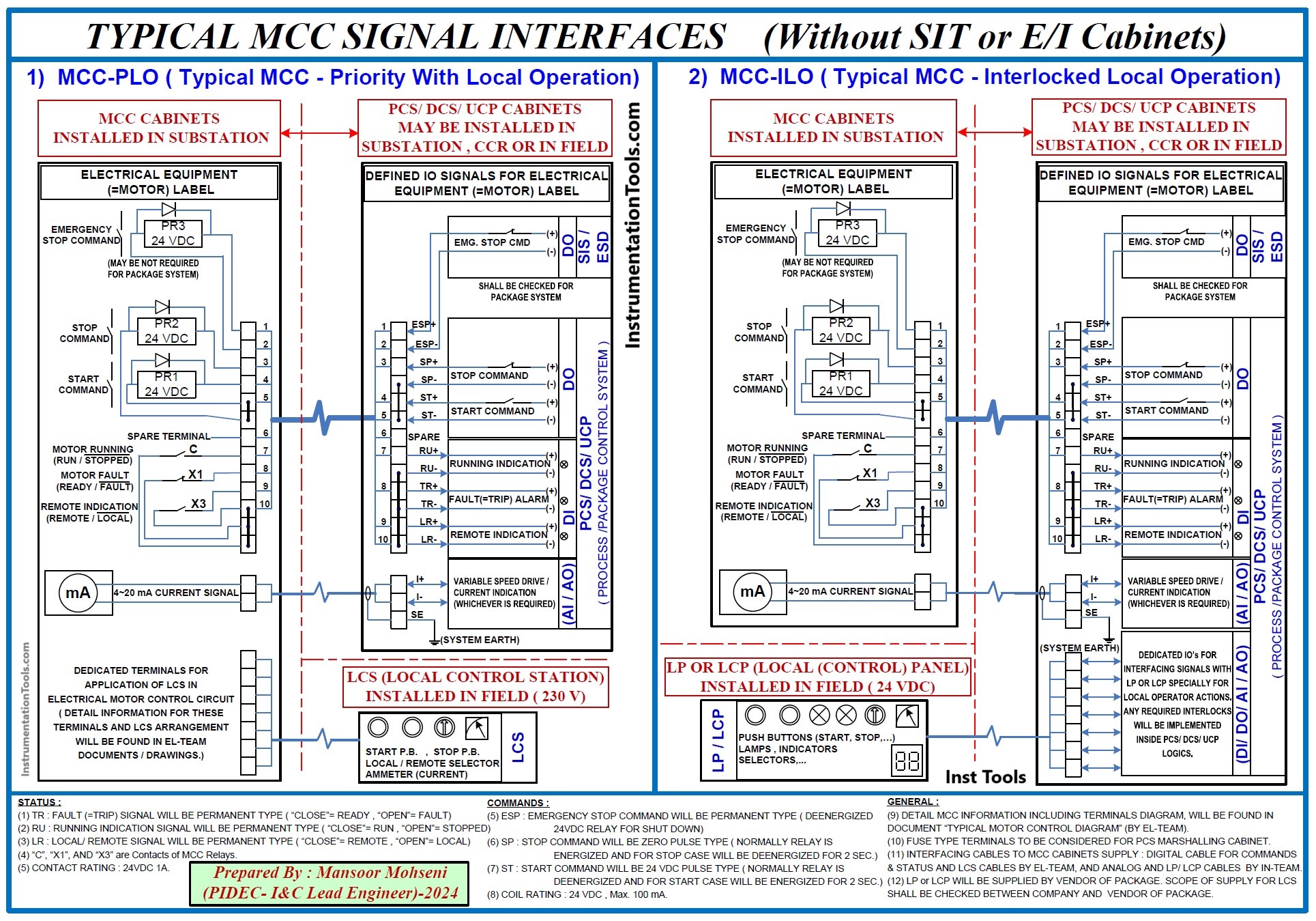
Figure-10: Sample of Typical MCC Signal Interfaces (Without SIT or E/I Cabinets).
The Typical MCC Signal Interfaces shown in the above Figures include both LCS (Local Control Stations) and LP/LCP (Local (Control) Panels) that are used for different modes of Motor Controls at the Field (Directly by MCC or via transferring by Process Control System). For more details on different possible Local Control modes or Configurations explanation read the article “Motor Control Signal Interface”
Figures 9 and 10 are just two Typical Prepared Samples of MCC Signal Interfaces provided for one (realistic) project while they may be more complex or on the contrary simpler in other projects.
As an example in some Process Plants Projects, it is possible to not have any ESD/SIS Signals for tripping (shut down) the motors, or vice versa in some other Process Plants they may have additional interfacing signals with Process Plant Control and Safety Systems (like Start Permit and Forward/ Reverse Commands, or Running Feedback and Motor Protection Feedback to ESD/SIS). Also for those Motors that have Variable Speed Drive (VSD or VFD) the dedicated interfacing signals agreement may be defined accordingly.
Package Systems Signal Interfaces With MCC Circuits
In Process Plants Projects it is possible to have some Process/ Unit Packages with their own Control and Safety Systems and also some Electric Motors which shall be controlled by such systems. So developing Package Systems may have effects on different Signals and Electrical drive considerations by I&C and Electrical teams too, and accordingly will affect their documents and activities.
For example, Figures 9 and 10 are prepared based on consideration of uniform Package Signal Interfaces to MCC Circuits same as plant Motors, while in some Process Plant projects it is not true, and dedicated Typical Interfacings may be agreed upon and considered (with separate sheets).
However Package Interfaces with MCC Circuits shall be studied carefully and during the project progress (and after receiving Package Vendor’s Documents) may need considering some new agreements between I&C and EL Teams (with Package Vendor).
Preparation and Development of Motor Control Diagrams Documents
Based on different possible Typical Motor Controls shown on P&ID documents and after making agreements with the I&C-Team for implementing Signal Interfaces with MCC, the Electrical Team will be enabled to prepare and define the different possible project MCC Circuits and reflect the results in Typical Motor Control Diagrams document.
Such documents shall include (typical) diagrams for details of implementing MCC Circuits for all motors that exist in the Process Plant Project. Such diagrams will be the core document requirements for transferring data to MCC Vendor(s).
However such documents may be used as basic documents for checking on correct circuit implementation by vendor and also future site troubleshooting. It is clear that based on the different conditions and requirements of each motor, such documents may include different levels of complexity as shown in Figures 11 and 12.
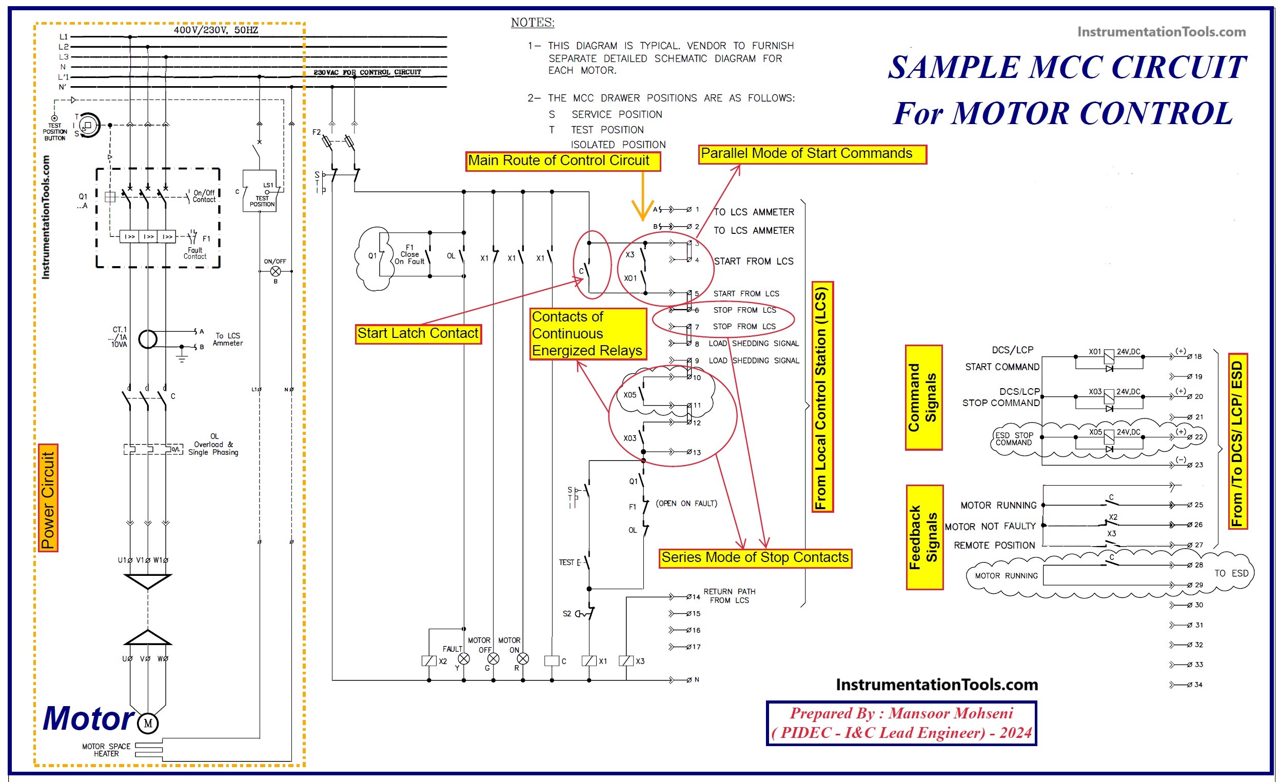
Figure-11: Sample of Simple Typical MCC Circuit for Motor Control.
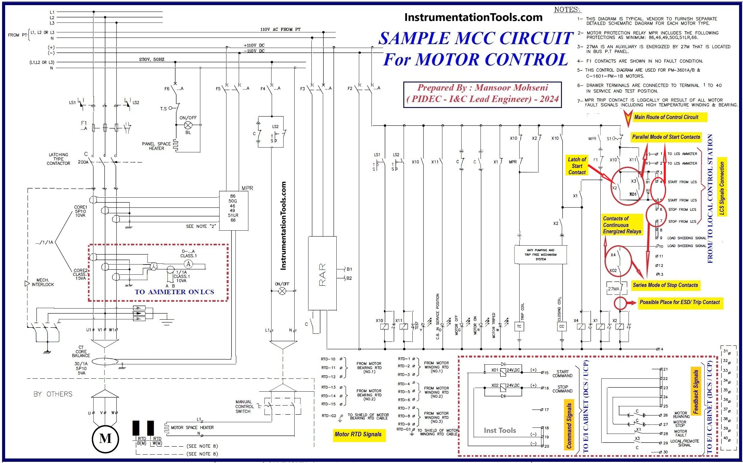
Figure-12: Sample of Normal Typical MCC Circuit for Motor Control.
Typical Motor Control Diagrams document will be developed by the Electrical Team and will be reviewed by the I&C-Team for any probable comments, especially for considering of right signal interfaces and proper reserved terminals for interconnections with systems (DCS/ESD/PLC/UCP…) as reflected in MCC Signal Interfaces (agreement) document.
More detail on motor signal interface considerations in Typical MCC Circuit design may be found in the reference article.
Purchasing and Construction of MCC Circuits
Based on the prepared Motor Control Schedule and Typical Motor Control Diagrams documents with additional project information, data, and conditions relevant requisitions will be activated for purchasing and construction of Electrical items by Electrical-Team. Such requisitions include Motors, MCC Circuits, Feeder Switching Panels, Cables, LCSs, Transformers, etc.
After finalizing vendor documents and supplying of required items, they will be transferred to the project site for installation and commissioning.
Figures 13 and 14 show some typical supplied items for MCC Circuits.
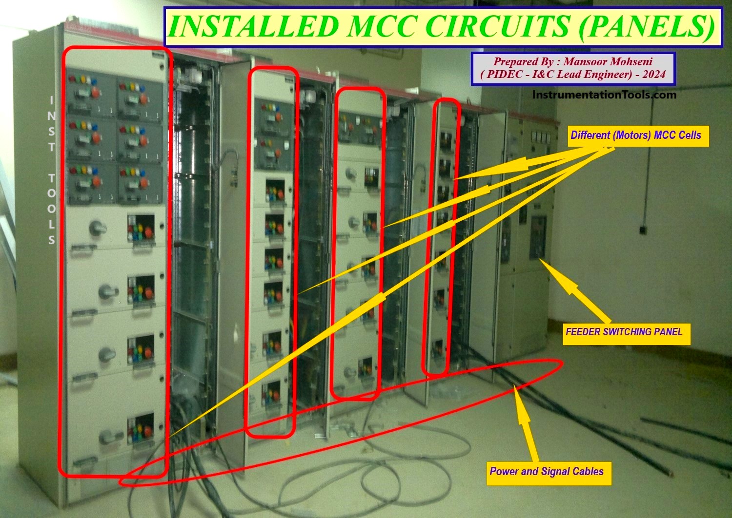
Figure-13: Installed MCC Circuits (Panels).
As Figure-13 shows some groups of MCC cells (based on provided calculations and classifications) are arranged and constructed in MCC Panels and will be fed from suitable considered electrical power feeder(s). Such arrangement of MCC Cells also shall be provided based on logical considerations for ease of operation and maintenance (for a group of motors with the same functions).
Figure-14 shows the considered area for power and signal cable terminations for MCCs.
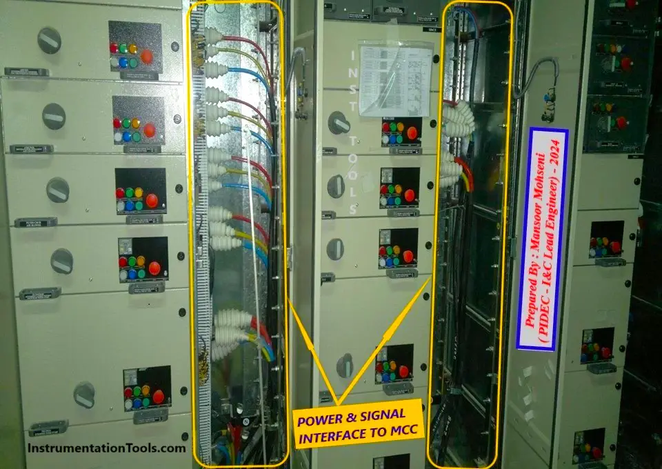
Figure-14: Considered Termination for Power and Signal Cables of MCC Circuits.
Purchasing and Construction of Control & Safety Systems with Relevant SIT Considerations
I&C-Team based on the provided data and calculations and further information and conditions will provide requisitions for project requirements on systems, instruments, and auxiliary items. By selecting vendors, reviewing, and finalizing vendor documents such mentioned items will be transferred to the project site.
One such subject is SIT Panels which is provided based on considered Process Control (System) Philosophy and provided SIT Design. Signal Interface Termination (SIT) is the final point for transferring Motor Control Signals from systems to MCC Circuits.
Other Interactions for Motor Control
Further to above mentioned sequence of activities and documents I&C and Electrical Teams shall have some interactions and coordination on their scopes of designs and implementations in order to finalize the required facilities for implementing Motors Control.
Generally, most of such activities are relevant to cablings and designing the cable routes up to reaching Motors, LCSs, LP/LCP, and Instruments (relevant to motors). Also, the layout design of Substation/ MCC Rooms may need close coordination of both teams based on considered SIT mode and area.
Another part of their close interactions is related to items for finalizing Process Package subjects of the project (especially relevant to Motors Control).
References:
- Motor Control Signal Interface
- Motor Control Center Signal Interface Termination
- Instrumentation and Electrical Teams Design Interactions
- Interactions With Process Control Systems Philosophy
