Inst ToolsInst ToolsInst Tools
  • Ask
  • Courses
  • Videos
  • Q & A
    • Interview
      • Instrumentation
      • Electronics
      • Electrical
      • Practical Questions
    • MCQ
      • Instrumentation MCQ
      • Electrical MCQ
      • Electronics MCQ
      • Control Systems MCQ
      • Analog Electronics MCQ
      • Digital Electronics MCQ
      • Power Electronics MCQ
      • Microprocessor MCQ
      • Multiple Choice Questions
  • EE
    • Electronics
      • Electronics Q & A
      • Electronic Basics
      • Electronic Devices & Circuits
      • Electronics Animation
      • Digital Electronics
    • Electrical
      • Electrical Basics
      • Electrical Q & A
      • Power Electronics
      • Electrical Machines
      • Electrical Animation
      • Power Systems
      • Switchgear & Protection
      • Transmission & Distribution
  • Measure
    • Control Valves
    • Calibration
    • Temperature
    • Pressure
    • Flow
    • Level
    • Analyzers
    • Switches
    • Vibration
    • Solenoid Valve
  • Control
    • PLC Tutorials
    • Control Systems
    • Safety Instrumented System (SIS)
    • Communication
    • Fire & Gas System
  • More
    • Design
    • Tools
    • Animation
    • Basics
    • Formulas
    • Standards
    • TextBooks
    • Common
    • Software
    • Excel Tools
    • Erection & Commissioning
    • Process Fundamentals
    • Videos
    • Books
Search
All rights reserved. Reproduction in whole or in part without written permission is prohibited.
Reading: DeMorgan’s Theorems using Ladder Diagram
Share
Notification Show More
Font ResizerAa
Inst ToolsInst Tools
Font ResizerAa
  • Courses
  • PLC Tutorials
  • Control Systems
Search
  • Ask
  • Courses
  • Videos
  • Q & A
    • Interview
    • MCQ
  • EE
    • Electronics
    • Electrical
  • Measure
    • Control Valves
    • Calibration
    • Temperature
    • Pressure
    • Flow
    • Level
    • Analyzers
    • Switches
    • Vibration
    • Solenoid Valve
  • Control
    • PLC Tutorials
    • Control Systems
    • Safety Instrumented System (SIS)
    • Communication
    • Fire & Gas System
  • More
    • Design
    • Tools
    • Animation
    • Basics
    • Formulas
    • Standards
    • TextBooks
    • Common
    • Software
    • Excel Tools
    • Erection & Commissioning
    • Process Fundamentals
    • Videos
    • Books
Follow US
All rights reserved. Reproduction in whole or in part without written permission is prohibited.
Inst Tools > Blog > PLC Tutorials > DeMorgan’s Theorems using Ladder Diagram

DeMorgan’s Theorems using Ladder Diagram

Last updated: March 4, 2021 3:51 pm
Editorial Staff
PLC Tutorials
1 Comment
Share
3 Min Read
SHARE

DeMorgan theorem is used in digital electronics. Explain the De Morgan theorem using PLC ladder language.

Contents
DeMorgan’s TheoremsExplanationList of Inputs/OutputsList of InputsList of OutputsMemory coilPLC Ladder ProgrammingNETWORK 1 :-NETWORK 2 :-NETWORK 3 :-NETWORK 4 :-NETWORK 5 :-NETWORK 6 :-

DeMorgan’s Theorems are two additional simplification techniques that can be used to simplify Boolean expressions. Again, the simpler the Boolean expression the simpler the resulting the Boolean expression, the simpler the resulting logic

DeMorgan’s Theorems Formula

DeMorgan’s Theorems

DeMorgan's Theorems

Explanation

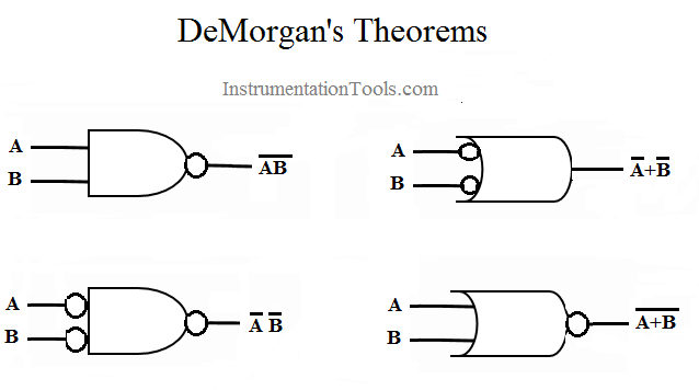
De Morgan theorem provides equality between NAND gate and negative OR gate and the equality between the NOR gate and the negative AND gate.

For example, take two variables A and B. The theorem is mathematical stated as, AB=A+B. The complement of the two variables is equal to the OR of complements of individual variables.

Second theorem is stated as: The complement of two variables ORed is equal to the AND of the complements of the individual variables.

List of Inputs/Outputs

List of Inputs

  • I1 :- A
  • I2 :- B

List of Outputs

  • Q1 :- OP 1
  • Q2 :- OP 2
  • Q3 :- OP 3
  • Q4 :- OP 4

Memory coil

  • M2 :- Memory coil for AND operation
    M3 :- Memory coil for OR operation

PLC Ladder Programming

NETWORK 1 :-

AND operation is used as shown in below figure. Result will be stored in M2 coil.

AND logic is used in DeMorgan PLC logic

NETWORK 2 :-

Inverse logic is used for DeMorgan first law as per below figure. It will generate inverse output (Q1).

Inverse logic is used for DeMorgan first law using PLC

NETWORK 3 :-

Two NC contact of variable A and variable B are connected in OR connection. Result will be Q3.

PLC DeMorgan theorem

Note :- LOGIC OPERATION OF Q1 AND Q3 ARE EQUAL AS PER LAW.

NETWORK 4 :-

Combination of two variables. Result will be stored in M3 variable.

DeMorgan Logic using PLC

NETWORK 5 :-

Inverse logic is used. Output Q2 will work inversely as per the law.

OR logic is used in DeMorgan PLC logic

NETWORK 6 :-

NC contacts of two variables are used in this network in AND gate.

AND logic is used in DeMorgan PLC logic

NOTE:-THE LOGIC OPERATION OF Q2 AND Q4 IS EQUAL AS PER LAW.

Note :- The above application may be different from actual application. This example is only for explanation and educational purpose only. We can implement this logic in other PLC. This is the simple concept of De Morgan theorems using ladder logic, we can use this concept in other examples.

All parameters and graphical representations considered in this example are for explanation purpose only, parameters or representation may be different in actual applications. All interlocks are not considered in the application.

Author : Bhavesh

If you liked this article, then please subscribe to our YouTube Channel for PLC and SCADA video tutorials.

You can also follow us on Facebook and Twitter to receive daily updates.

Read Next:

PLC Troubleshooting

PLC Conveyor Program

Motor Logic using PLC

PLC Practical Tests

Switches, Routers, Firewalls

Don't Miss Our Updates
Be the first to get exclusive content straight to your email.
We promise not to spam you. You can unsubscribe at any time.
Invalid email address
You've successfully subscribed !
Motor Feedback Fail Logic in PLC
Remote Factory Acceptance Test
Example PLC Program to Control a Pump based on Level Sensors
Structured Text PLC Programming for Two-Tanks Level Application
What are Trends in SCADA?
Share This Article
Facebook Whatsapp Whatsapp LinkedIn Copy Link
Share
1 Comment
  • jeff says:
    October 26, 2023 at 10:44 pm

    nor is not equivalent to inverted nand, inverted nand is or

    Reply

Leave a Reply Cancel reply

Your email address will not be published. Required fields are marked *

Stay Connected

128.3kFollowersLike
69.1kFollowersFollow
208kSubscribersSubscribe
38kFollowersFollow

Categories

Recent Comments

  • Guifty Shimica on Top Non-PLC Certification Courses for Automation Professionals
  • Guifty Shimica on Top Non-PLC Certification Courses for Automation Professionals
  • MIHARITSOA Aina Sitraka on Top Non-PLC Certification Courses for Automation Professionals
  • Vaishnavi on Free Instrumentation Course for Trainee Engineers

Related Articles

PLC Cooking Timer Example for Kitchen Automation

PLC Cooking Timer Example for Kitchen Automation

Commissioning Checklist for Industrial Automation System

Commissioning Checklists for Industrial Automation Systems

PLC Emergency Stop Example Program

PLC Emergency Stop Example Program

How a PLC communicates with Transmitters

How PLC Reads the Data from Field Transmitters

scada hmi

Functions of SCADA

Siemens Communication between PLCs using I-Device

Tutorial: Siemens Communication between PLCs using I-Device

Types of PLC

#14 PLC Best Practices – Restrict Third-party Data Interfaces

Allen Bradley PLC Emulator

How to Work with Allen Bradley RsLogix Emulator?

More Articles

calibrating low-pressure instrument

Simulate Different Values for Pressure Instrument Under Test

Reasons to Calibrate Flowmeters

Reasons to Calibrate Different Types of Flow Meters

Interview Questions on Control Valves

Interview Questions on Control Valves

Gas Detectors Calibration

Calibration of Gas Detectors

Electrical Machines Questions and Answers

Hunting and Damper Windings Questions

Encoders and Decoders Objective Questions

Encoders and Decoders Objective Questions

Electrical Machines Questions and Answers

MCQ on Rotating Electrical Machines

Ball Valve root cause

Ammonia Feed Ball Valve to Ship Tank Closed

Follow US
All rights reserved. Reproduction in whole or in part without written permission is prohibited.
Welcome Back!

Sign in to your account

Username or Email Address
Password

Lost your password?