Inst ToolsInst ToolsInst Tools
  • Courses
  • Automation
    • PLC
    • Control System
    • Safety System
    • Communication
    • Fire & Gas System
  • Instrumentation
    • Design
    • Pressure
    • Temperature
    • Flow
    • Level
    • Vibration
    • Analyzer
    • Control Valve
    • Switch
    • Calibration
    • Erection & Commissioning
  • Interview
    • Instrumentation
    • Electrical
    • Electronics
    • Practical
  • Q&A
    • Instrumentation
    • Control System
    • Electrical
    • Electronics
    • Analog Electronics
    • Digital Electronics
    • Power Electronics
    • Microprocessor
Search
  • Books
  • Software
  • Projects
  • Process
  • Tools
  • Basics
  • Formula
  • Power Plant
  • Root Cause Analysis
  • Electrical Basics
  • Animation
  • Standards
  • 4-20 mA Course
  • Siemens PLC Course
Reading: De-energize to Safe Loop philosophy
Share
Notification Show More
Font ResizerAa
Inst ToolsInst Tools
Font ResizerAa
  • Courses
  • Design
  • PLC
  • Interview
  • Control System
Search
  • Courses
  • Automation
    • PLC
    • Control System
    • Safety System
    • Communication
    • Fire & Gas System
  • Instrumentation
    • Design
    • Pressure
    • Temperature
    • Flow
    • Level
    • Vibration
    • Analyzer
    • Control Valve
    • Switch
    • Calibration
    • Erection & Commissioning
  • Interview
    • Instrumentation
    • Electrical
    • Electronics
    • Practical
  • Q&A
    • Instrumentation
    • Control System
    • Electrical
    • Electronics
    • Analog Electronics
    • Digital Electronics
    • Power Electronics
    • Microprocessor
Follow US
All rights reserved. Reproduction in whole or in part without written permission is prohibited.
Inst Tools > Blog > Control Systems > De-energize to Safe Loop philosophy

De-energize to Safe Loop philosophy

Last updated: June 20, 2019 10:56 pm
Editorial Staff
Control Systems Safety Instrumented System (SIS)
1 Comment
Share
2 Min Read
SHARE

Safety Instrument loop in a plant operate in two modes:

  1. Energized to safe
  2. De-energized to safe

De-energize to safe loop, also known as fail safe system means that during plant normal condition, there will be electrical current flows through the instrument loop. When trip/shutdown is required, then loop will be de-energized.

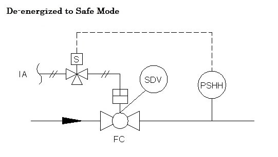
De-energize to safe loop

De-energized to safe loop

See illustration on above picture of a simple unit consisting Pressure Switch High High and SDV. During plant normal condition the pressure switch contact is closed (pressure is lower than HiHi setting) and enables current flow within the loop.

Likewise, the solenoid of SDV is energized by electrical power to allow air supply stroking the SDV and then forcing it in open position.

As long as the control/safety system receiving current signal of pressure switch loop, plant is considered as normal. If the pressure increases and reaches HiHi (High High setpoint) setting, pressure switch will activate and contact changes from close to open and there will be no current flows, hence alarming plant control system.

The predetermined executive action shall then be taken to put system in safe condition i.e. de-energize the SDV’s solenoid to make the main valve close.

The reason de-energized to safe mode to be implemented in such system is to make it in safer state (in above case by closing the main valve) when either one of the following conditions occurs:

  • Unintended instrument cable disconnection (either pressure switch or solenoid valve)
  • Electrical black out

Articles You May Like :

What is a Active Barrier ?

Alarm Management System

How does SCADA Works ?

Transmitter Calibration

PLC Program for Lamp

Don't Miss Our Updates
Be the first to get exclusive content straight to your email.
We promise not to spam you. You can unsubscribe at any time.
Invalid email address
You've successfully subscribed !

Continue Reading

Integral Controller Principle
What is Ground, and importance of a Grounding System?
Hardwired I/O and Serial I/O – Differences Explained
What is a Control Loop ?
Configuration of PlantPAx Library in Factory Talk Studio
Modbus Function Codes and Addresses
Share This Article
Facebook Whatsapp Whatsapp LinkedIn Copy Link
Share
1 Comment
  • Murthy M says:
    September 4, 2015 at 5:09 am

    Hi Sir, Thank You for the explanation.

    Reply

Leave a Reply Cancel reply

Your email address will not be published. Required fields are marked *

Stay Connected

128.3kFollowersLike
69.1kFollowersFollow
208kSubscribersSubscribe
38kFollowersFollow

Categories

Explore More

Demo of a SCADA Software – Level Control System
Layers of Protection Analysis (LOPA) Interview Questions
Add On Instructions Programming – Analog Input Devices in Studio 5000
Why Bias used in Proportional Controller ?
SCADA & Telemetry Systems
Why choose Intrinsic Safety ?
Flowmeter Control Strategy
ESDV : How it Works ?

Keep Learning

Variable Speed Control of Propulsion Motor for VSI and CSI type Frequency Converters

Speed Control of Ship Electrical Motor Propulsion

transmitters shared for BPCS and SIS

SIS Instrument Sharing – Transmitters Shared for BPCS and SIS Example

Why Grounding

Basics of Grounding

redundant transmitters

SIS Sensors

DeltaV System Configuration Change and Download - 3

DeltaV System Configuration Changes and Download

Library of PlantPAx Process Objects

How to Download PlantPAx Library?

4 TO 20 MA ANALOG CURRENT SIGNALS

Basics of 4 to 20 mA analog Signals

Distributed Control System Architecture

Control System Architecture

Learn More

DTS sensors

Distributed Temperature Sensors (DTS) in Power Lines

Nano Instrumentation Objective Questions

Nano Instrumentation Objective Questions

Types of Industrial Relays

What is a Relay? Types of Industrial Relays

Vortex Flow Meter Principle

Vortex Flow meter Animation

Transmitters 4-20mA Current Failure Alarm Limits

Transmitters 4-20mA Current Failure Alarm Limits

Feedback Transducer System Objective Questions

Feedback Transducer System Objective Questions

Transformers Questions & Answers Part-2

Transformers Questions & Answers Part-2

Sounding Level Transmitter Working Animation

Follow US
All rights reserved. Reproduction in whole or in part without written permission is prohibited.
Welcome Back!

Sign in to your account

Username or Email Address
Password

Lost your password?