All of the rules governing DC circuits that have been discussed so far can now be applied to analyze complex DC circuits. To apply these rules effectively, loop equations, node equations, and equivalent resistances must be used.
Node Equations
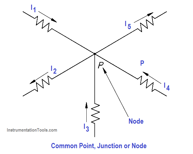
Kirchhoff’s current law, as previously stated, says that at any junction point in a circuit the current arriving is equal to the current leaving. Let us consider five currents entering and leaving a junction shown as P (Figure 43). This junction is also considered a node.
Assume that all currents entering the node are positive, and all currents that leave the node are negative. Therefore, I1 ,I3 , and I4 are positive, and I2 and I5 are negative. Kirchhoff’s Law also states that the sum of all the currents meeting at the node is zero. For Figure 43, Below Equation represents this law mathematically.
I1 + I2 + I3 + I4 + I5 = 0
Figure 43 Node Point
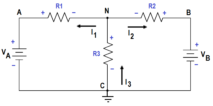
By solving node equations, we can calculate the unknown node voltages. To each node in a circuit we will assign a letter or number. In Figure 44, A, B, C, and N are nodes, and N and C are principal nodes. Principal nodes are those nodes with three or more connections. Node C will be our selected reference node.
VAC is the voltage between Nodes A and C; VBC is the voltage between Nodes B and C; and VNC is the voltage between Nodes N and C. We have already determined that all node voltages have a reference node; therefore, we can substitute VA for VAC , VB for VBC , VN for VNC.
Figure 44 Circuit for Node Analysis
Assume that loop currentsI1 and I2 leave Node N, and that I3 enters Node N (Figure 44).
From Kirchhoff’s current law:
∑ I = 0
I1 + I2 + I3 = 0
I3 = I1 + I2
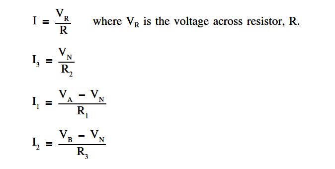
Using Ohm’s Law and solving for the current through each resistor we obtain the following.
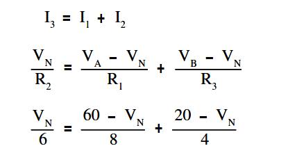
Substitute these equations for I1 ,I2 , and I3 into Kirchhoff’s current equation yields the following.
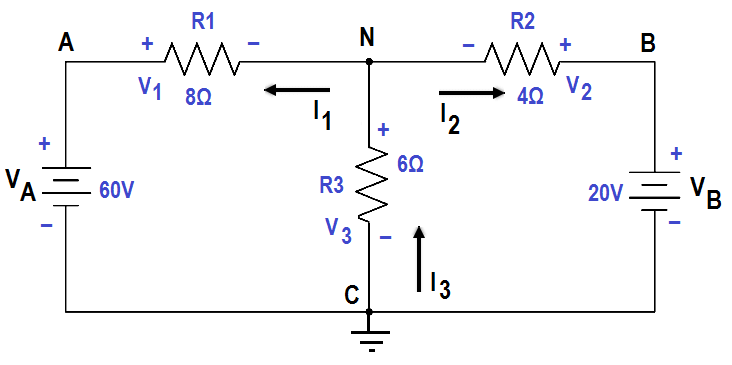
The circuit shown in Figure 45 can be solved for voltages and currents by using the node-voltage analysis.
Figure 45 Node – Voltage Analysis
First, assume direction of current flow shown. Mark nodes A, B, C, and N, and mark the polarity across each resistor.
Second, using Kirchhoff’s current law at Node N, solve for VN.
Clear the fraction so that we have a common denominator:
4VN = 3 (60 – VN) + 6 (20 – VN)
4VN= 180 – 3VN + 120 – 6VN
13VN = 300
VN = 23.077
Third, find all voltage drops and currents.
V1 = VA – VN = 60 – 23.077 = 36.923 Volts
V2 = VN = 23.077 Volts
V3 = VB – VN = 20 – 23.077 = -3.077 Volts
The negative value for V3 shows that the current flow through R3 is opposite that which was assumed and that the polarity across R3 is reversed.
I1 = V1/R1 = 36.923 / 8 = 4.65 amp
I2 = V2/R2 = 23.077 / 6 = 3.846 amp
I3 = V3/R3 = -3.077 / 4 = – 0.769 amp
The negative value for I3 shows that the current flow through R3 is opposite that which was assumed.
