This article will discuss the use of data comparison instructions in the Omron PLC with a practical example. This system will utilize the Binary Increment instruction to increment the data count and the Binary Decrement instruction to decrement the data count. Data comparison instructions will be used to turn on a Lamp when the conditions specified by the instructions are met. In this system, the comparison instructions used will include Equal To (=), Not Equal To (≠), Greater Than (>), Less Than (<), Greater Than or Equal To (≥), and Less Than or Equal To (≤).
Program Objective
Examples of Comparison Operators:
- Equal To Operator (=): Indicates that two values are exactly the same.
- Not Equal To Operator (≠): Indicates that two values are not the same (could be greater or smaller).
- Greater Than Operator (>): The value on the left is greater than the value on the right.
- Less Than Operator (<): The value on the left is less than the value on the right.
- Greater Than or Equal To Operator (≥): The value on the left is greater than or equal to the value on the right.
- Less Than or Equal To Operator (≤): The value on the left is less than or equal to the value on the right.
Program Steps
- When the trigger button (+) is pressed, the data will increase, and when the trigger button (-) is pressed, the data will decrease.
- If the data value is greater than “1”, Lamp 1 will turn ON; if the value is less than “1”, Lamp 2 will turn ON.
- If the data value is zero “0”, Lamp3 will turn ON.
- If the data value is greater than or equal to “4”, Lamp 4 will turn ON.
- If the data value is less than or equal to “4” and greater than “2”, Lamp 5 will turn ON.
Data Comparison Instructions in Omron PLC
Mapping Details
| S.No. | Comment | Input (I) | Output (Q) | Memory Bit | Memory Word |
|---|---|---|---|---|---|
| 1 | START | 0.00 | |||
| 2 | STOP | 0.01 | |||
| 3 | (+)_TRIGGER | 0.02 | |||
| 4 | (-)_TRIGGER | 0.03 | |||
| 5 | LAMP_1 | 100.00 | |||
| 6 | LAMP_2 | 100.01 | |||
| 7 | LAMP_3 | 100.02 | |||
| 8 | LAMP_4 | 100.03 | |||
| 9 | LAMP_5 | 100.04 | |||
| 10 | COUNTER_DATA | D0 | |||
| 11 | SYSTEM_ON | W0.00 |
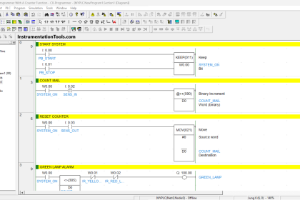
PLC Programming
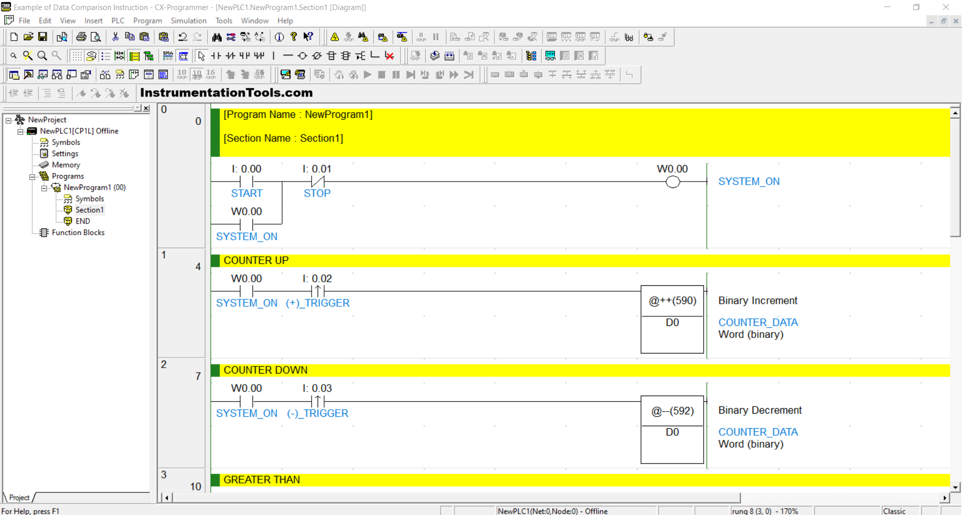
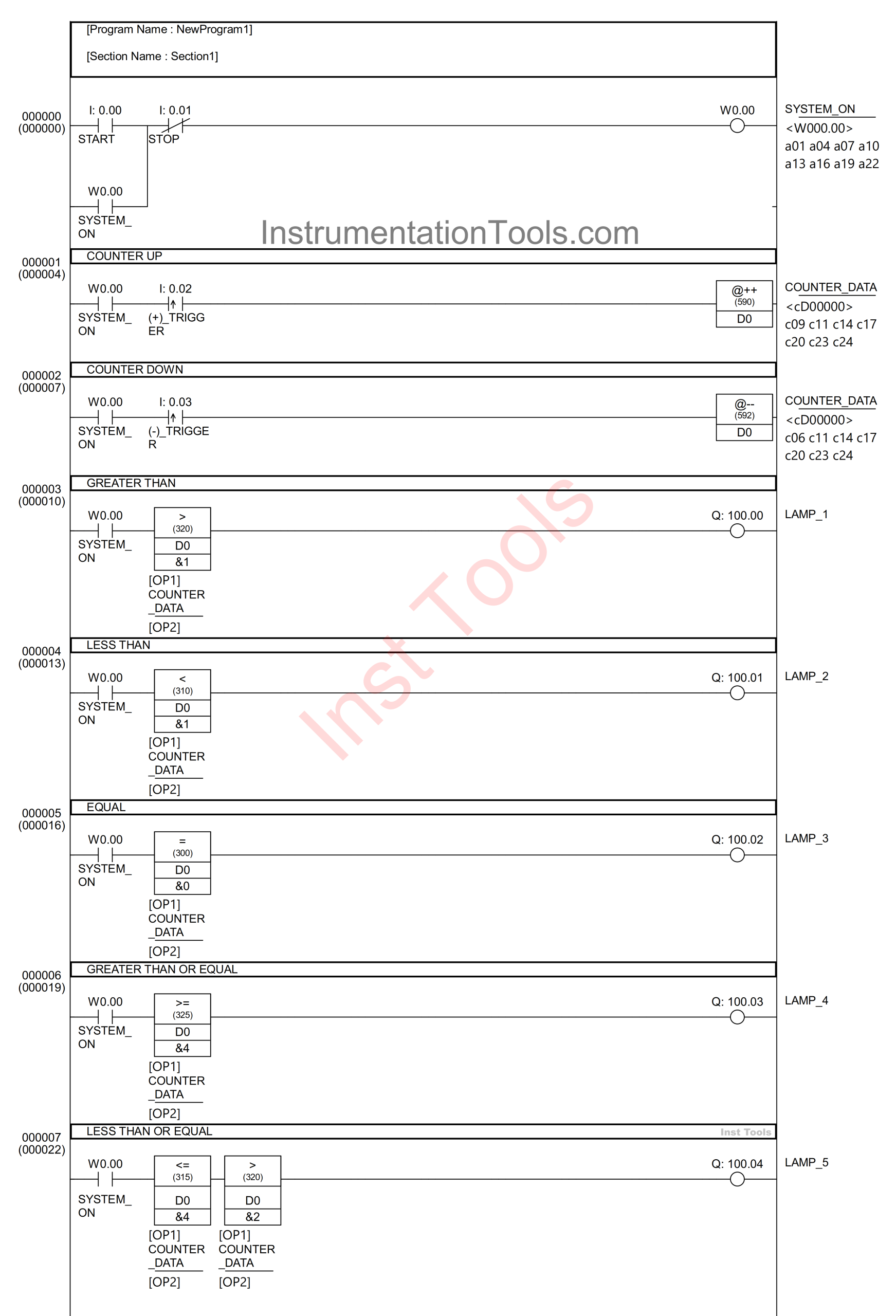
RUNG 0 (SYSTEM_ON)
In this Rung, if the START (0.00) button is pressed, the memory bit SYSTEM_ON (W0.00) will be in a HIGH state. Because it uses Latching, the memory bit SYSTEM_ON (W0.00) will remain in a HIGH state even though the PB_START (0.00) button has been released.
The memory bit SYSTEM_ON (W0.00) will return to a LOW state if the STOP (0.01) button is pressed.
RUNG 1 (COUNTER UP)
In this rung, when the NO contact of the memory bit SYSTEM_ON (W0.00) is in a HIGH state and the (+)_TRIGGER (0.02) button is pressed, the value in the memory word COUNTER_DATA (D0) will increase by +1 due to the use of the Binary Increment / @++ (590) instruction.
The Binary Increment / @++ (590) instruction will add (+1) to the memory word data when triggered.
RUNG 2 (COUNTER DOWN)
In this rung, when the NO contact of the memory bit SYSTEM_ON (W0.00) is in a HIGH state and the (-)_TRIGGER (0.03) button is pressed, the value in the memory word COUNTER_DATA (D0) will decrease by -1 due to the use of the Binary Decrement / @– (592) instruction.
The Binary Decrement / @– (592) instruction will subtract (-1) from the memory word data when triggered.
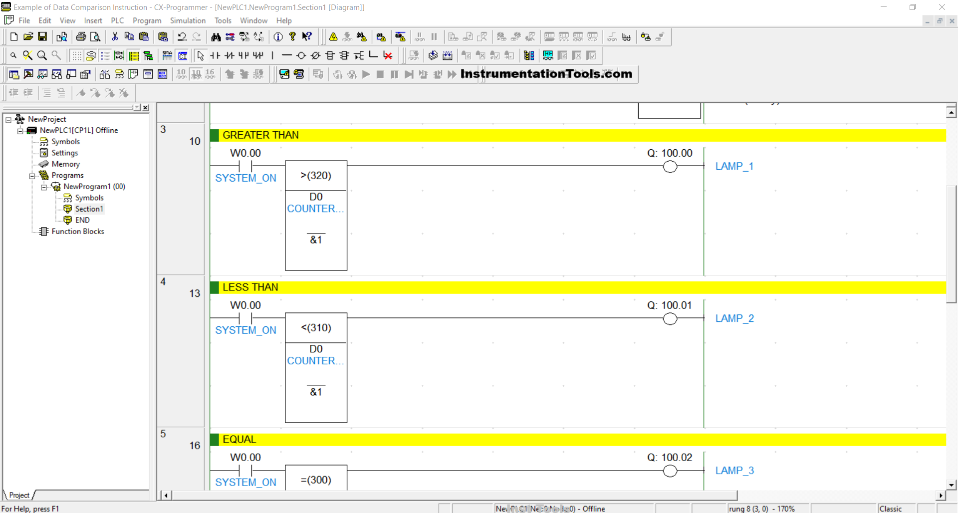
RUNG 3 (GREATER THAN)
In this Rung, if the contact NO of the memory bit SYSTEM_ON (W0.00) is in the HIGH state and the value in the memory word COUNTER_DATA (D0) is Greater Than “1”, then the output LAMP_1 (100.00) will be ON.
RUNG 4 (LESS THAN)
In this Rung, if the NO contact of the memory bit SYSTEM_ON (W0.00) is in the HIGH state and the value in the memory word COUNTER_DATA (D0) is Less Than “1”, then the output LAMP_2 (100.01) will be ON.
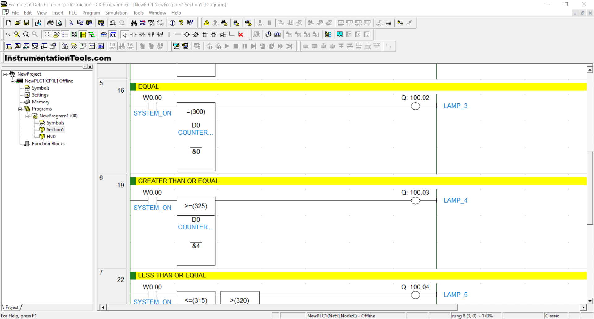
RUNG 5 (EQUAL)
In this Rung, if the contact NO of the memory bit SYSTEM_ON (W0.00) is in the HIGH state and the value in the memory word COUNTER_DATA (D0) is Equal To “0”, then the output LAMP_3 (100.02) will be ON.
RUNG 6 (GREATER THAN OR EQUAL)
In this Rung, if the NO contact of the memory bit SYSTEM_ON (W0.00) is in the HIGH state and the value in the memory word COUNTER_DATA (D0) is Greater Than or Equal To “4”, then the LAMP_4 (100.03) output will be ON.
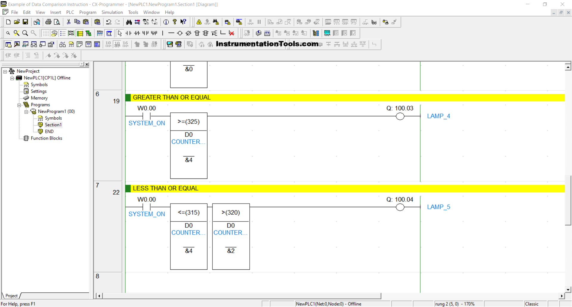
RUNG 7 (LESS THAN OR EQUAL)
In this Rung, if the NO contact of the memory bit SYSTEM_ON (W0.00) is in HIGH state and the value of the memory word COUNTER_DATA (D0) is Less Than or Equal To “4” and Greater Than “2”, then the LAMP_5 (100.04) output will be ON.
Read Next:
- Siemens PLC Comparator Programming Logic
- Schneider PLC Programming Example for Beginners
- PLC Programming Example on Multiple LEDs using Set Coil
- Difference Between CompactLogix and ControlLogix
- How to Convert an Electrical Diagram into a PLC Program?