Inst ToolsInst ToolsInst Tools
  • Courses
  • Automation
    • PLC
    • Control System
    • Safety System
    • Communication
    • Fire & Gas System
  • Instrumentation
    • Design
    • Pressure
    • Temperature
    • Flow
    • Level
    • Vibration
    • Analyzer
    • Control Valve
    • Switch
    • Calibration
    • Erection & Commissioning
  • Interview
    • Instrumentation
    • Electrical
    • Electronics
    • Practical
  • Q&A
    • Instrumentation
    • Control System
    • Electrical
    • Electronics
    • Analog Electronics
    • Digital Electronics
    • Power Electronics
    • Microprocessor
  • Request
Search
  • Books
  • Software
  • Projects
  • Process
  • Tools
  • Basics
  • Formula
  • Power Plant
  • Root Cause Analysis
  • Electrical Basics
  • Animation
  • Standards
  • 4-20 mA Course
  • Siemens PLC Course
Reading: Siemens S7 300 CPU Status and LED Errors Explanation
Share
Font ResizerAa
Inst ToolsInst Tools
Font ResizerAa
  • Courses
  • Design
  • PLC
  • Interview
  • Control System
Search
  • Courses
  • Automation
    • PLC
    • Control System
    • Safety System
    • Communication
    • Fire & Gas System
  • Instrumentation
    • Design
    • Pressure
    • Temperature
    • Flow
    • Level
    • Vibration
    • Analyzer
    • Control Valve
    • Switch
    • Calibration
    • Erection & Commissioning
  • Interview
    • Instrumentation
    • Electrical
    • Electronics
    • Practical
  • Q&A
    • Instrumentation
    • Control System
    • Electrical
    • Electronics
    • Analog Electronics
    • Digital Electronics
    • Power Electronics
    • Microprocessor
  • Request
Follow US
All rights reserved. Reproduction in whole or in part without written permission is prohibited.
Inst Tools > Blog > PLC Tutorials > Siemens S7 300 CPU Status and LED Errors Explanation

Siemens S7 300 CPU Status and LED Errors Explanation

Last updated: March 4, 2021 12:14 pm
Editorial Staff
PLC Tutorials
4 Comments
Share
2 Min Read
SHARE

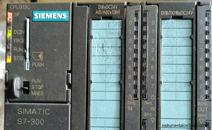
In Siemens S7 300 CPUs, there is a series of LED lights with different colors which shows us the modes, status, and errors of the PLC.

Contents
S7 300 LED ErrorsSFBFMAINTDC5VFRCERunSTOP

S7 300 LED Errors

Siemens S7 300 CPU Status and LED Errors Explanation

SF

System fault: it indicates there is an error in the system, this error could be software error like an error in programming or hardware error like a power loss of one of the input modules

Color: Steady Red

BF

Bus Fault: it indicates that there is an error in the system network, like a bad contact in one of the communication connectors, or there is an overlap between the addresses in the network

Color: Steady Red

MAINT

Maintenance: where ever this indicator energized this means that the CPU is not working anymore and needs a service, but this is rarely happening.

Color: Steady yellow

DC5V

This led indicates that there is a 24 Volt DC provided to the CPU.

Color: Steady Green

FRCE

Force: it indicates that at least one of the PLC inputs or outputs is forced to on or off.

Color: Steady yellow

Run

Run mode is on whenever the CPU is working properly without any troubles, and flashes in the startup of the CPU.

Color: Steady Green

STOP

a.

When the CPU is in STOP mode or there is a software/hardware error.

Color: Steady yellow

b.

For a memory reset request when inserting the memory card.

Color: Yellow flashes slowly

c.

When the memory reset is being carried out.

Color: Yellow flashes quickly

Author: Karim Ali Anwar

If you liked this article, then please subscribe to our YouTube Channel for PLC and SCADA video tutorials.

You can also follow us on Facebook and Twitter to receive daily updates.

Read Next:

  • Problems with TON Timer
  • Analogy of Ohm’s Law
  • As-found and As-left Calibration
  • Workstation Healthiness Checks
  • Programmable Logic Controller
Don't Miss Our Updates
Be the first to get exclusive content straight to your email.
We promise not to spam you. You can unsubscribe at any time.
Invalid email address
You've successfully subscribed !

Continue Reading

Parking Lights PLC Program Explained with Video
Always ON and OFF Bit using Ladder Logic and Statement List
While Do Statement in Structured Text PLC Program
What is PLC Redundancy?
PLC Programming Example for a Batch Process
What is PCS 7?
Share This Article
Facebook Whatsapp Whatsapp LinkedIn Copy Link
Share
4 Comments
  • John Quintero says:
    May 27, 2020 at 6:43 am

    Hello Karim, thank you very much for your explanation about the S7 300. Have a great day.

    Reply
  • Raghu Ram Gudela says:
    July 31, 2022 at 12:31 pm

    What if all the indications flashes at a time? Can anyone explain me about this?

    Reply
  • Nana Frimpong says:
    July 13, 2023 at 11:48 am

    APPRECITED WITH THE UPDATE ON S7-300-LED ERRORS.
    THANK YOU.

    Reply
  • MD.Raju says:
    August 21, 2023 at 9:30 am

    In CPU 315 2PN/DP
    if all indicator LED light same time glowing with out blinking what is the problem??
    Thank you

    Reply

Leave a Reply Cancel reply

Your email address will not be published. Required fields are marked *

Stay Connected

128.3kFollowersLike
69.1kFollowersFollow
210kSubscribersSubscribe
38kFollowersFollow

Categories

Explore More

PLC Program to Control Gas Pressure using Closed-Loop
Upload Option Disabled in Siemens PLC
Communication between Wincc and Tia Portal
Programmable Logic Controller Quiz
Global Acknowledgment Instruction in Safety PLC
How to Create Faceplate in FactoryTalk View Studio?
PLC Digital Input and Digital Output Modules
What are Faceplates? How to Create a Faceplate? HMI Visualization

Keep Learning

How to Choose HMI

How to Choose a Suitable HMI for Your Application?

PLC Multiple Choice Questions

PLC Multiple Choice Questions

Communicate between the PLC program and HMI program

Design a Program Using Studio 5000 and FactoryTalk View Studio

Latched and Momentary Operation of Motor PLC Program

Latched and Momentary Operation of Motor PLC Program

Principle of Operation of PLC

Principle of Operation of PLC

On Delay Timer TON in Tia Portal

Timers in PLC Programming – Siemens Tia Portal Tutorials

Sample Schematic Template for Systems Architecture Diagram

Design Document for Project Systems Architecture

PLC programming for liquid mixing application code

PLC Mixing Logic in Liquids on EcoStruxure Machine Expert-Basic

Learn More

Top 100 Power Plant Engineering Objective Questions & Answers

Top 100 Power Plant Engineering Objective Questions & Answers

Power Electronics Objective Questions

AC Voltage Controllers Quiz

Burnout Function in Temperature Transmitter

Burnout Function in Temperature Transmitter

Control Valve Positioners

Control Valve Positioners

Diode-vi-characteristic-curve-for-forward-bias

VI Characteristic of a Diode

Power Electronics Objective Questions

Single Phase Voltage Source Inverter (VSI) Objective Questions

Liquid In Glass Thermometers

Liquid In Glass Thermometer Principle

What is Swing Check Valve ?

Menu

  • About
  • Privacy Policy
  • Copyright

Quick Links

  • Learn PLC
  • Helping Hand
  • Part Time Job

YouTube Subscribe

Follow US
All rights reserved. Reproduction in whole or in part without written permission is prohibited.
Welcome Back!

Sign in to your account

Username or Email Address
Password

Lost your password?