Here you will learn how to create ladder diagram from Boolean logic and understand the basics of PLC.
Note: The PLC example shown here is for educational use only for students to understand PLC ladder diagrams.
Create Ladder Diagram
Problem Statement
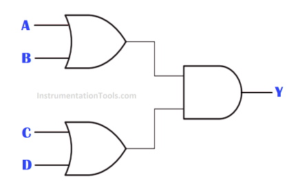
Design a PLC ladder logic for the following Boolean Expression.
We are using toggle Inputs to control the output.
Find out the equivalent ladder logic for the given boolean logic.
Y= AB+CD
Video
This video tutorial helps you to learn the creation of ladder diagram based on the given boolean expression.
Digital Inputs
The inputs listed below.
A: I0.0
B: I0.1
C: I0.2
D:I0.3
Digital Outputs
The outputs listed below.
Y: Q0.0
Boolean Logic Ladder Diagram
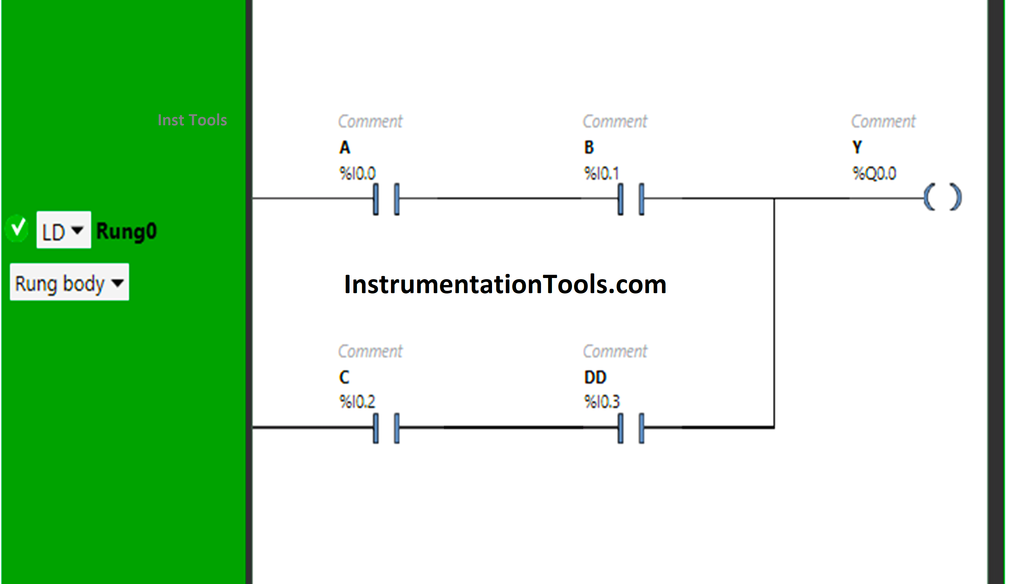
Program Description
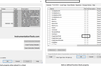
- We used Schneider Electric EcoStruxure Machine Expert Basic software.
- In the above program, Normally Open Contacts are used for input A, input B, input C and input D.
- Input A and Input B are connected in series, thus implementing AND Logic Gate.
- There is again the implementation of AND Logic Gate as Input C and Input D are connected in series.
- There is also implementation of OR Logic Gate as AB and CD are connected in parallel.
- For the output Y (Q0.0) to be ON, Input A and Input B should be ON.
- Turning ON only one input i.e., either input A or input B will not turn ON the output Y (Q0.0).
- Turning ON Input C and Input D will also turn ON the output Y (Q0.0).
- If only one input i.e., either input C or input D is turned ON, then the output Y (Q0.0) will remain OFF.
Logic Result
Check the below logic output result with simulation.
When both Input A and Input B are ON
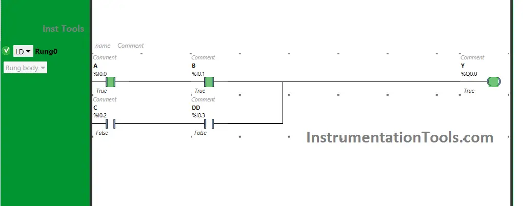
The signal will pass through Input A and Input B when turned ON. If only one input i.e., Input A or Input B is turned ON, the output Y (Q0.0) will not turn ON.
The inputs A and B are in series and are used as Normally Open Contacts. So, for the output Y (Q0.0) both the inputs i.e., input A and input B should be ON.
When both Input C and Input D are ON
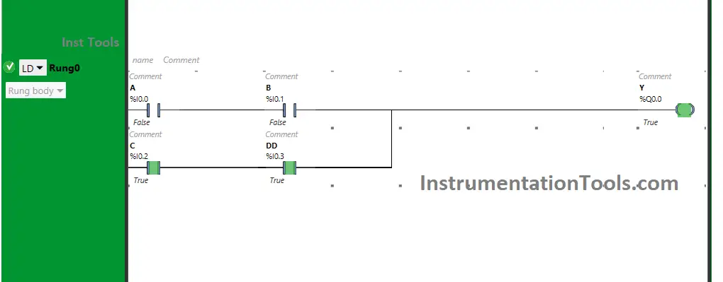
When Input C and Input D are turned ON, the output Y(Q0.0) will turn ON. Input C and Input D implement AND Logic Gate as these are connected in series and are taken as Normally open Conatacts.
When both the inputs i.e., input C and input D are turned ON, then only the output Y (Q0.0) will turn ON, If only one input is turned ON i.e., only input C or input D is turned ON, the the output Y (Q0.0) will not turn ON.
If you liked this article, please subscribe to our YouTube Channel for PLC and SCADA video tutorials.
You can also follow us on Facebook and Twitter to receive daily updates.
Read Next:
- Types of Electrical Industrial Relays
- Project System Architecture Documents
- Double-acting Pneumatic Cylinder Logic
- Transferring Data Across PLC Systems
- Omron PLC Programming Training Course