This article discusses the product sorting and counting system on conveyors with color detection using PLC logic. This PLC system will sort and collect products in storage based on the color of the product carried by the conveyor, each product has its own storage.
Conveyor Sorting System with Color Detection
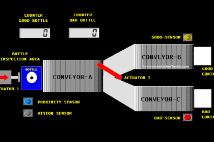
The conveyor will carry products in 3 different colors (RED, BLUE, YELLOW). This Product Sorting and Counting System has sensors that will sort products based on color. The sensor will Activate if it detects a product with a Matching color.
When the sensor is Active, the Storage Gate will Open to collect the product. Every product detected will be counted by the system, when the quantity of products reaches the maximum storage limit, the Conveyor will Stop and the alarm will turn On.
Program Objective
This program has 5 buttons and 3 sensors:
- The PB_ON (0.00) button is used to turn ON the system.
- The PB_OFF (0.01) button is used to turn OFF the system.
- The RESET_COUNT_RED (0.05) button is used to Reset the RED product counter data in the memory word COUNT_RED_PRODUCT (D0).
- The RESET_COUNT_BLUE (0.06) button is used to Reset the BLUE product counter data in the word memory COUNT_BLUE_PRODUCT (D1).
- The RESET_COUNT_YELLOW (0.07) button is used to Reset the YELLOW product counter data in the memory word COUNT_YELLOW_PRODUCT (D2).
- The SENS_RED (0.02) sensor is used to detect Red products.
- The SENS_BLUE (0.03) sensor is used to detect Blue products.
- The SENS_YELLOW (0.04) sensor is used to detect Yellow products.
In this PLC program, when the PB_ON (0.00) button is pressed, the system will Run and the CONVEYOR Output (100.00) will be ON. The Conveyor will carry products in 3 different colors (RED, BLUE, YELLOW).
When the System Detects a Red Product
When the SENS_RED (0.02) sensor detects a Red product, the Red Storage Gate RED_GATE (100.04) will OPEN for 5 seconds and then CLOSE again. The quantity of products will be recorded in the memory word COUNT_RED_PRODUCT (D0).
When the System Detects a Blue Product
When the SENS_BLUE (0.03) sensor detects a Blue product, the Blue Storage Gate BLUE_GATE (100.05) will OPEN for 5 seconds and then CLOSE again. The number of quantities will be recorded in the memory word COUNT_BLUE_PRODUCT (D1).
When the System Detects a Yellow Product
When the SENS_YELLOW (0.04) sensor detects a Yellow product, the Yellow Storage Gate YELLOW_GATE (100.06) will OPEN for 5 seconds and then CLOSE again. The quantity of products will be recorded in the memory word COUNT_YELLOW_PRODUCT (D2).
Alarms
If one of the alarms is on, the conveyor will stop.
- Red Product Storage Alarm RED_ALARM (100.01) will be ON if the quantity of products has reached 20.
- The Blue Product Storage Alarm BLUE_ALARM (100.02) will be ON if the quantity of products has reached 25.
- Yellow Product Storage Alarm YELLOW_ALARM (100.03) will be ON if the quantity of products has reached 30.

Address Details
| Comment | Input (I) | Output (Q) | Memory Word | Memory Bits | Timer |
| PB_ON | 0.00 | ||||
| PB_OFF | 0.01 | ||||
| SENS_RED | 0.02 | ||||
| SENS_BLUE | 0.03 | ||||
| SENS_YELLOW | 0.04 | ||||
| RESET_COUNT_RED | 0.05 | ||||
| RESET_COUNT_BLUE | 0.06 | ||||
| RESET_COUNT_YELLOW | 0.07 | ||||
| CONVEYOR | 100.00 | ||||
| RED_ALARM | 100.01 | ||||
| BLUE_ALARM | 100.02 | ||||
| YELLOW_ALARM | 100.03 | ||||
| RED_GATE | 100.04 | ||||
| BLUE_GATE | 100.05 | ||||
| YELLOW_GATE | 100.06 | ||||
| COUNT_RED_PRODUCT | D0 | ||||
| COUNT_BLUE_PRODUCT | D1 | ||||
| COUNT_YELLOW_PRODUCT | D2 | ||||
| TIMER_RED | T0000 | ||||
| TIMER_BLUE | T0001 | ||||
| TIMER_YELLOW | T0002 | ||||
| SYSTEM_ON | W0.00 |
PLC Logic
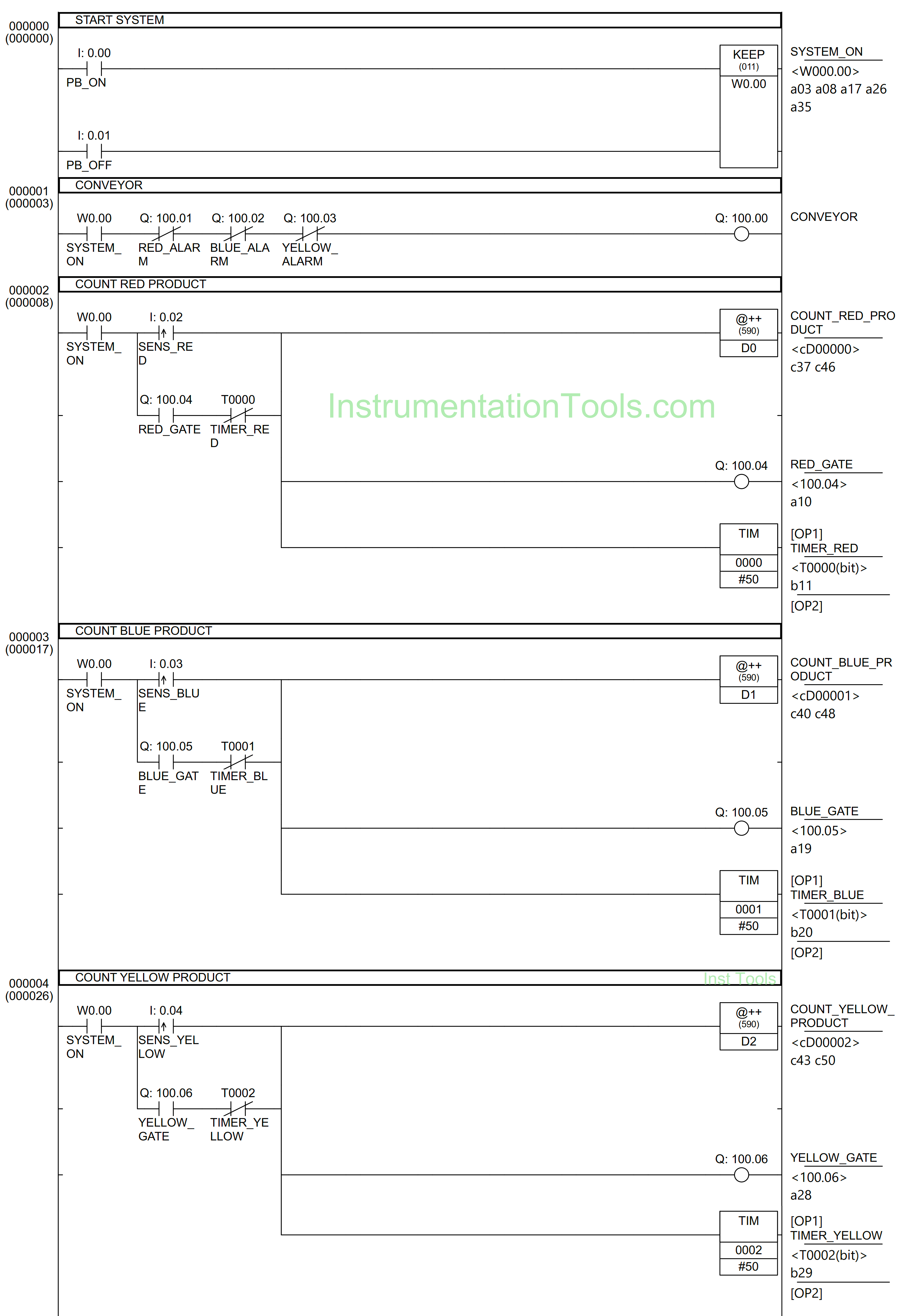
RUNG 0 (START SYSTEM)
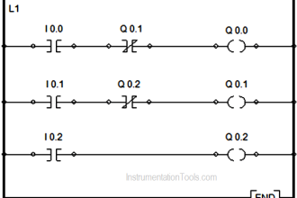
In this Rung, when the PB_ON (0.00) button is pressed, the memory bit SYSTEM_ON (W0.00) will be in the HIGH state. Because the KEEP(011) instruction is used, the memory bit SYSTEM_ON (W0.00) remains in the HIGH state even though the PB_ON (0.00) button has been Released.
The memory bit SYSTEM_ON (W0.00) will become a LOW state if the PB_OFF (0.01) button is Pressed.
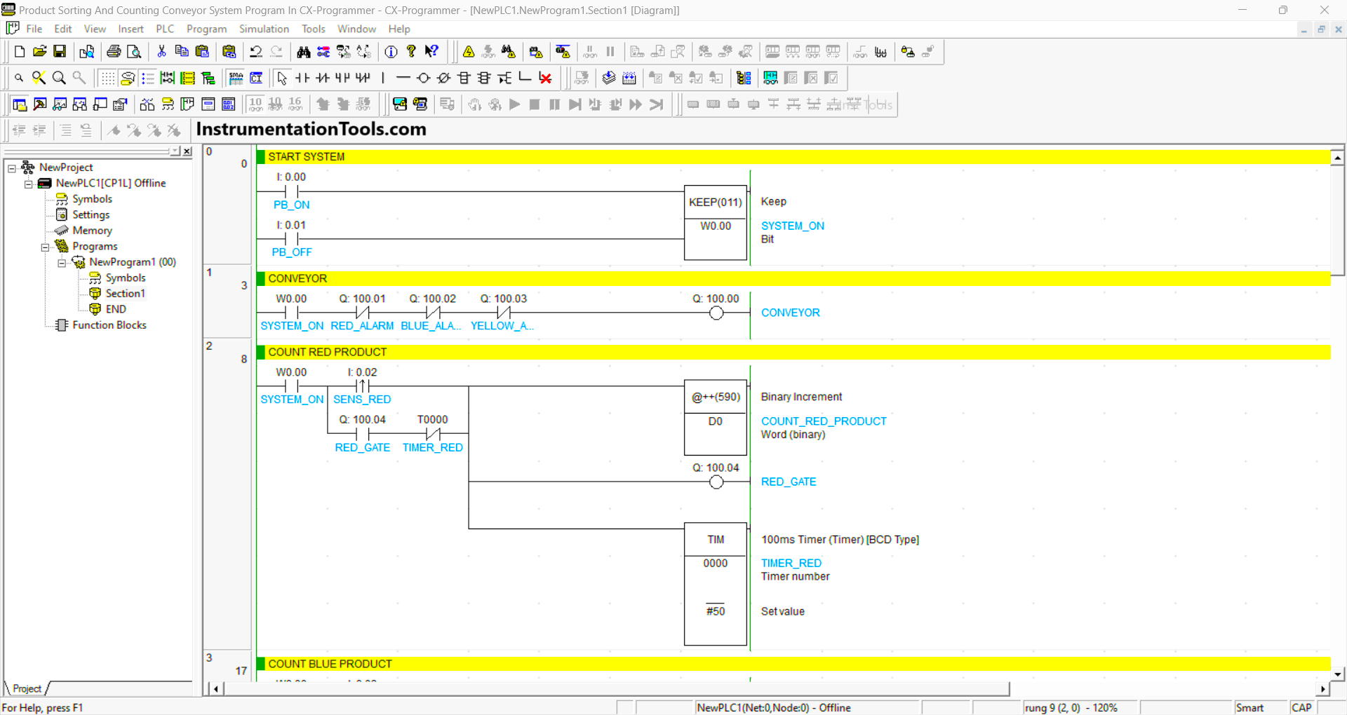
RUNG 1 (CONVEYOR)
In this Rung, when the NO contact of memory bit SYSTEM_ON (W0.00) is in the HIGH state, the CONVEYOR (100.00) Output will be ON.
The CONVEYOR (100.00) output will be OFF if the NC contact of RED_ALARM (100.01) or BLUE_ALARM (100.02) or YELLOW_ALARM (100.03) is ON.
RUNG 2 (COUNT RED PRODUCT)
In this Rung, when the NO contact of memory bit SYSTEM_ON (W0.00) and SENS_RED (0.02) sensor in the HIGH state, then the data in memory word COUNT_RED_PRODUCT (D0) will increase (+1) and the Output RED_GATE (100.04) will ON.
The timer TIMER_RED (T0000) will count up to 5 seconds and after it has finished counting, the RED_GATE (100.04) output will be OFF.
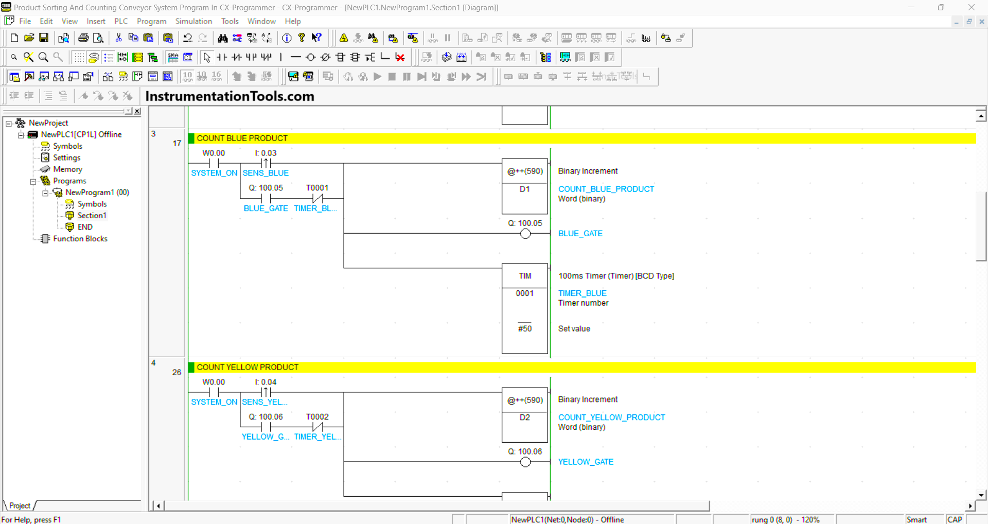
RUNG 3 (COUNT BLUE PRODUCT)
In this Rung, when the NO contact of memory bit SYSTEM_ON (W0.00) and sensor SENS_BLUE (0.03) in the HIGH state, then the data in memory word COUNT_BLUE_PRODUCT (D1) will increase (+1) and the BLUE_GATE (100.05) Output will be ON.
The timer TIMER_BLUE (T0001) will count up to 5 seconds and after it has finished counting, the BLUE_GATE (100.05) output will be OFF.
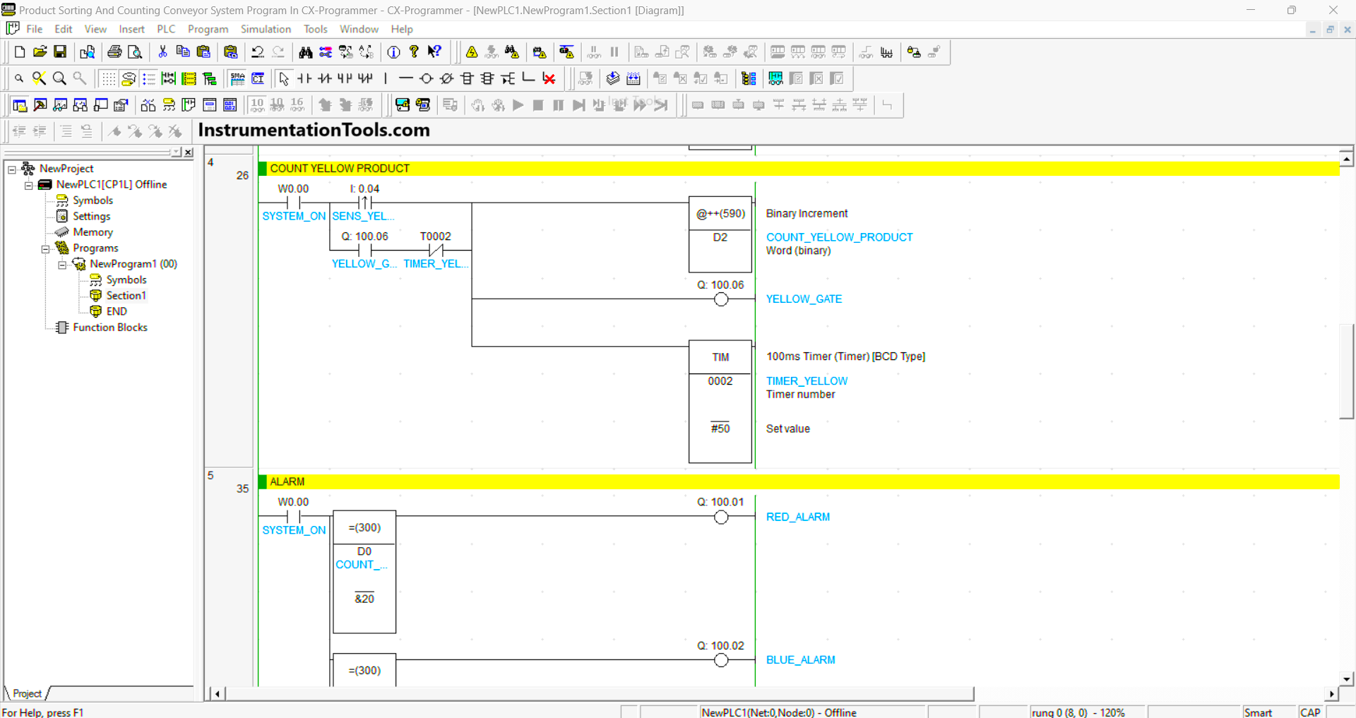
RUNG 4 (COUNT YELLOW PRODUCT)
In this Rung, when the NO contact of memory bit SYSTEM_ON (W0.00) and sensor SENS_YELLOW (0.04) in the HIGH state, then the data in memory word COUNT_ YELLOW_PRODUCT (D2) will increase (+1) and the output YELLOW_GATE (100.06) will ON.
The timer TIMER_ YELLOW (T0002) will count up to 5 seconds and after it has finished counting, the YELLOW_GATE (100.06) output will be OFF.
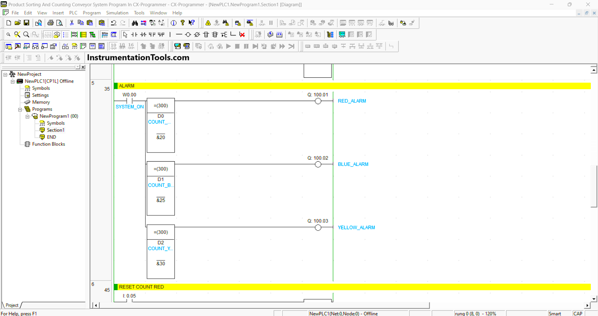
RUNG 5 (ALARM)
In this Rung, when the NO contact of memory bit SYSTEM_ON (W0.00) and the value in memory word COUNT_RED_PRODUCT (D0) is equal to “20”, then the Output RED_ALARM (100.01) will be ON.
When the value in memory word COUNT_BLUE_PRODUCT (D1) is equal to “25”, then the Output BLUE_ALARM (100.02) will be ON.
When the value in memory word COUNT_YELLOW_PRODUCT (D2) is equal to “30”, then the Output YELLOW_ALARM (100.03) will be ON.

RUNG 6 (RESET COUNT RED)
In this rung, when the RESET_COUNT_RED (0.05) button is pressed, the data in the memory word COUNT_RED_PRODUCT (D0) will be Reset to zero “0”.
RUNG 7 (RESET COUNT BLUE)
In this rung, when the RESET_COUNT_BLUE (0.06) button is pressed, the data in the memory word COUNT_BLUE_PRODUCT (D1) will be Reset to zero “0”.
RUNG 7 (RESET COUNT YELLOW)
In this rung, when the RESET_COUNT_YELLOW (0.07) button is pressed, the data in the memory word COUNT_YELLOW_PRODUCT (D2) will be Reset to zero “0”.
Read Next:
- Automatic Railway Crossing Gate PLC Logic
- Bread Oven Control Auto Mode PLC Logic
- Dosing Pump PLC Programming Logic
- PLC Programming 3 Motors with Priority
- PLC Crane Movement Control Program