Inst ToolsInst ToolsInst Tools
  • Courses
  • Automation
    • PLC
    • Control System
    • Safety System
    • Communication
    • Fire & Gas System
  • Instrumentation
    • Design
    • Pressure
    • Temperature
    • Flow
    • Level
    • Vibration
    • Analyzer
    • Control Valve
    • Switch
    • Calibration
    • Erection & Commissioning
  • Interview
    • Instrumentation
    • Electrical
    • Electronics
    • Practical
  • Q&A
    • Instrumentation
    • Control System
    • Electrical
    • Electronics
    • Analog Electronics
    • Digital Electronics
    • Power Electronics
    • Microprocessor
  • Request
Search
  • Books
  • Software
  • Projects
  • Process
  • Tools
  • Basics
  • Formula
  • Power Plant
  • Root Cause Analysis
  • Electrical Basics
  • Animation
  • Standards
  • 4-20 mA Course
  • Siemens PLC Course
Reading: Control Valve Performance with Constant Pressure
Share
Notification Show More
Font ResizerAa
Inst ToolsInst Tools
Font ResizerAa
  • Courses
  • Design
  • PLC
  • Interview
  • Control System
Search
  • Courses
  • Automation
    • PLC
    • Control System
    • Safety System
    • Communication
    • Fire & Gas System
  • Instrumentation
    • Design
    • Pressure
    • Temperature
    • Flow
    • Level
    • Vibration
    • Analyzer
    • Control Valve
    • Switch
    • Calibration
    • Erection & Commissioning
  • Interview
    • Instrumentation
    • Electrical
    • Electronics
    • Practical
  • Q&A
    • Instrumentation
    • Control System
    • Electrical
    • Electronics
    • Analog Electronics
    • Digital Electronics
    • Power Electronics
    • Microprocessor
  • Request
Follow US
All rights reserved. Reproduction in whole or in part without written permission is prohibited.
Inst Tools > Blog > Control Valves > Control Valve Performance with Constant Pressure

Control Valve Performance with Constant Pressure

Last updated: September 20, 2019 7:29 am
Editorial Staff
Control Valves
No Comments
Share
4 Min Read
SHARE

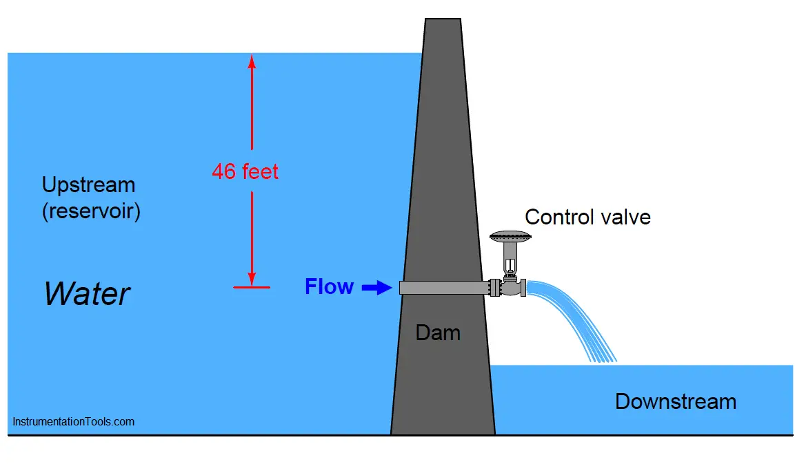
First, let us imagine a control valve installed at the base of a dam, releasing water from the reservoir. Given a constant height of water in the reservoir, the upstream (hydrostatic) pressure at the valve will likewise be constant.

Let’s assume this constant upstream pressure will be 20 PSI (corresponding to approximately 46 feet of water column above the valve inlet). With the valve discharging into the air, downstream pressure will essentially be zero.

This set of upstream and downstream conditions guarantees a constant pressure drop of 20 PSI across our control valve at all times, for all flow conditions:

Control Valve Performance with Constant Pressure

Control Valve Performance with Constant Pressure Drop

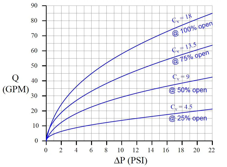
Furthermore, let us assume the control valve has a “linear” inherent characteristic and a maximum flow capacity (Cv rating) of 18. This means the valve’s Cv will be 18 at 100% open, 13.5 at 75% open, 9 at 50% open, 4.5 at 25% open, and 0 at fully closed (0% open).

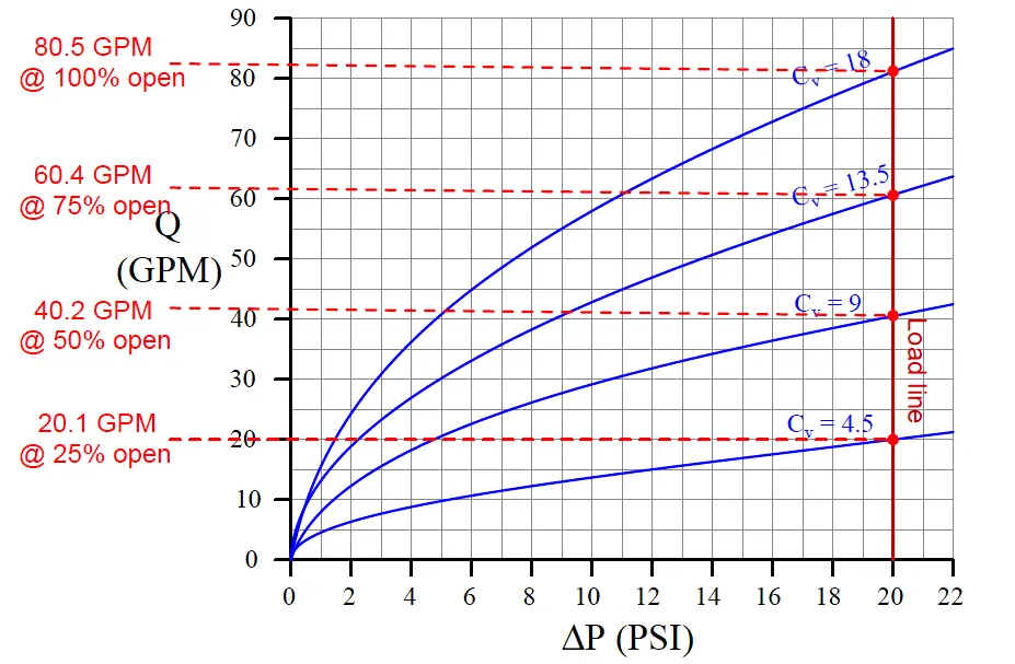
We may plot the behavior of this control valve at these four stem positions by graphing the amount of flow through the valve for varying degrees of pressure drop across the valve.

The result is a set of characteristic curves (Note) for our hypothetical control valve:

characteristic curves of control valve

Note : For those readers with an electronics background, the concept of “characteristic curves” for a control valve is exactly the same as that of characteristic curves for transistors. Instead of plotting the amount of current a bipolar transistor will pass through its collector terminal (IC) given varying amounts of collector-emitter voltage drop (VCE), we are plotting the rate of water flow through the valve (Q) given varying amounts of supply pressure (ΔP).

Each curve on the graph traces the amount of flow through the valve at a constant stem position, for different amounts of applied pressure drop.

For example, looking at the curve representing 50% open (Cv = 9), we can see the valve should flow about 42 GPM at 22 PSI, about 35 GPM at 15 PSI, about 20 GPM at 5 PSI, and so on. Of course, we can obtain these same flow figures simply by evaluating the formula Q = Cv√ΔP (which is in fact what I used to plot these curves), but the point here is to learn how to interpret the graph.

We may use this set of characteristic curves to determine how this valve will respond in any installation by superimposing another curve on the graph called a load line, describing the pressure drop available to the valve at different flow rates.

Since we know our hypothetical dam supplies a constant 20 PSI across the control valve for all flow conditions, the load line for the dam will be a vertical line at 20 PSI:

Control Valve flow conditions

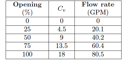
By noting the points of intersection between the valve’s characteristic curves and the load line, we may determine the flow rates from the dam at those stem positions:

valve’s characteristic curves table

If we were to graph this table, plotting flow versus stem position, we would obtain a very linear graph. Note how 50% open gives us twice as much flow as 25% open, and 100% open nearly twice as much flow as 50% open.

This tells us our control valve will respond linearly when operated under these conditions (i.e. operating with a constant pressure drop).
Articles You May Like :

Control Valve Questions and Answers

Turbine Flow Meter Verification

Types of Variable Area Flow Meters

Control Valve Trim Characteristics

Practical Pneumatic Instruments

Don't Miss Our Updates
Be the first to get exclusive content straight to your email.
We promise not to spam you. You can unsubscribe at any time.
Invalid email address
You've successfully subscribed !

Continue Reading

Pressure Safety Valve Leak Test Procedure (PSV Testing)
Solenoid Valve Troubleshooting Practices
Valve Interlock
What is Cavitation? What are the Causes?
SIS Final Control Elements
Types of Control Valve Trim
Share This Article
Facebook Whatsapp Whatsapp LinkedIn Copy Link
Share
Leave a Comment

Leave a Reply Cancel reply

Your email address will not be published. Required fields are marked *

Stay Connected

128.3kFollowersLike
69.1kFollowersFollow
210kSubscribersSubscribe
38kFollowersFollow

Categories

Explore More

Shaft and Coupling Bore Tapers Repair Caused Frequent Shutdowns
Basics of Control Valve Sizing
Refrigeration Compressor Turbine Not-tripping when needed Trip
How Globe Valves Work ?
Control Valve Passing Problem after Overhauling Job
Difference Between the Control Valve and Shut-off Valve
Constant Flow Valve Principle
Reversing Control Valve Actuator Fail Safe Mode

Keep Learning

Weir Diaphragm Valve

Diaphragm Valves Construction, Types, Stem & Bonnet Assembly

Control Valves Basic Theory

Control Valves Theory

30% Feed Control Valve

Purpose of 100% and 30% Feed Control Valves in a Power Plant

3-way solenoid valves control instrument air pressure

Solenoid Valve’s Energized or De-energized State ?

Common Valve Abbreviations

Common Valve Abbreviations in US Engineering Drawings

Ball Valve Parts

What is Ball Valve ?

Valve Actuator Passing

Lessons Learned from Actuator Passing Incidents

Choke Valve Hydro Test Setup

Choke Valve Hydro Testing Procedure

Learn More

Sequential Timer Control of Lamps

Schneider PLC Example: Control Lamps Sequences

Types of Circuit Breakers

Types of Circuit Breakers, Advantages, Disadvantages

Refrigeration Compressor Turbine Not-tripping when needed Trip

Refrigeration Compressor Turbine Not-tripping when needed Trip

Contact and Non-Contact Level Sensors

Contact and Non-Contact Level Sensors

Modbus ASCII and RTU Message Frame

Background of Modbus – ASCII and RTU Data Frames

Ion Spectrometers Questions & Answers

Ion Spectroscopy Questions & Answers

Voltage Drop in a Series Circuit

Series Resistance

Field Instrument 4-20mA Calculation

How to do 4-20mA Conversions Easily

Menu

  • About
  • Privacy Policy
  • Copyright

Quick Links

  • Learn PLC
  • Helping Hand
  • Part Time Job

YouTube Subscribe

Follow US
All rights reserved. Reproduction in whole or in part without written permission is prohibited.
Welcome Back!

Sign in to your account

Username or Email Address
Password

Lost your password?