Inst ToolsInst ToolsInst Tools
  • Courses
  • Automation
    • PLC
    • Control System
    • Safety System
    • Communication
    • Fire & Gas System
  • Instrumentation
    • Design
    • Pressure
    • Temperature
    • Flow
    • Level
    • Vibration
    • Analyzer
    • Control Valve
    • Switch
    • Calibration
    • Erection & Commissioning
  • Interview
    • Instrumentation
    • Electrical
    • Electronics
    • Practical
  • Q&A
    • Instrumentation
    • Control System
    • Electrical
    • Electronics
    • Analog Electronics
    • Digital Electronics
    • Power Electronics
    • Microprocessor
  • Request
Search
  • Books
  • Software
  • Projects
  • Process
  • Tools
  • Basics
  • Formula
  • Power Plant
  • Root Cause Analysis
  • Electrical Basics
  • Animation
  • Standards
  • 4-20 mA Course
  • Siemens PLC Course
Reading: Closed Tank Level Measurement using DP Transmitters
Share
Font ResizerAa
Inst ToolsInst Tools
Font ResizerAa
  • Courses
  • Design
  • PLC
  • Interview
  • Control System
Search
  • Courses
  • Automation
    • PLC
    • Control System
    • Safety System
    • Communication
    • Fire & Gas System
  • Instrumentation
    • Design
    • Pressure
    • Temperature
    • Flow
    • Level
    • Vibration
    • Analyzer
    • Control Valve
    • Switch
    • Calibration
    • Erection & Commissioning
  • Interview
    • Instrumentation
    • Electrical
    • Electronics
    • Practical
  • Q&A
    • Instrumentation
    • Control System
    • Electrical
    • Electronics
    • Analog Electronics
    • Digital Electronics
    • Power Electronics
    • Microprocessor
  • Request
Follow US
All rights reserved. Reproduction in whole or in part without written permission is prohibited.
Inst Tools > Blog > Level Measurement > Closed Tank Level Measurement using DP Transmitters

Closed Tank Level Measurement using DP Transmitters

Last updated: February 22, 2018 12:22 pm
Editorial Staff
Level Measurement
4 Comments
Share
6 Min Read
SHARE

Hydrostatic head instruments for measuring liquid level in vessels operating above atmospheric pressure uses the full capability of the differential pressure instruments with both sides of the measuring element connected to the vessel.

Closed Tank Level Measurement using DP Transmitter

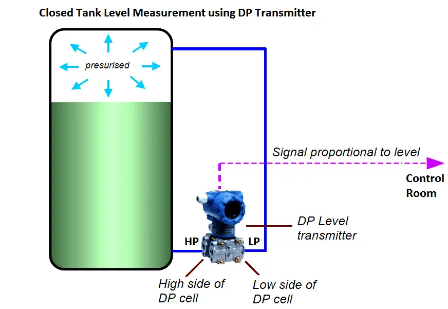
The differential pressure transmitter, enables an automatic subtraction of the pressure on the LP side, from the total pressure appearing at the HP side. This is accomplished as shown in diagram above, where the LP is connected above the maximum predicted level. With this arrangement, each increment of pressure above the liquid surface is applied to both capsule assemblies of the transmitter, and since they are in opposition, the increment is cancelled. Only the hydrostatic pressure, which is applied to the HP, is effective in causing any response to the transmitter, which is proportional to the level.

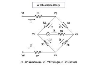
The DP transmitter have inbuilt pressure sensors like Diaphragm, capsules, strain gauges etc to measure the differential pressure. The pressure sensor converts the measured pressure into parameters like millivolts, capacitance, resistance etc depending on the type of pressure sensor we are using inside the DP transmitter. Generally a Wheatstone bridge will be used to convert resistance, capaciatance or inducatance type of pressure sensor outputs into electrical signal like millivolts or volts which is proportional to the pressure, then transmitter converts the pressure into equivalent Level Signal accordingly.

The tank bottom tapping point is High pressure (HP) tapping point and Tank top tapping is Low Pressure (LP) tapping point. The DP Transmitter is connected at these HP & LP tapping points accordingly.

The DP Transmitter calibration parameters will vary depending on installation & seal system also. Generally we can see three possibilities of installation of a transmitter in the field.

They are :

  1. Transmitter installed Exactly at HP tapping point ( Ideal & preferred way of installation)
  2. Transmitter installed above HP tapping point ( Not preferable, Chance of bubble formation in the impulse line)
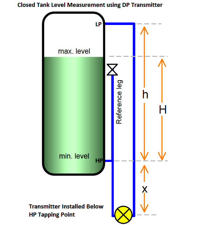
  3. Transmitter installed below HP tapping point (Error can be compensated effectively)

So we have to calibrate the transmitter depending on the type of installation in the field. The calibration formula will vary slightly depending on the installation.Every transmitter have two important parameters, they are Lower Range Value (LRV) & Upper Range Value (URV). We have to calculate the LRV & URV values based on type of installation. The below figures with formulas dictates the calculations. After calculating the values, configure the same parameters in the transmitter using HART communicator.

Here we are discussing two types : Wet Leg & Dry Leg

Wet Leg : if LP impulse line is filled with liquid like water, glycol, glycerin or liquid inside tank

Dry Leg : if LP impulse line is filled with air, gas or any other gases.

The hydro static pressures applying on DP transmitters will vary depending on wet leg or dry leg. so we have to consider these & calibration formula also varies accordingly.

We can only decide for a particular DP transmitter is having Wet leg or Dry leg from the field installation & its process application. Sometimes we can make a dry leg installation into wet leg by filling water into the LP impulse line also.

Transmitter mounted leveled with the min. level
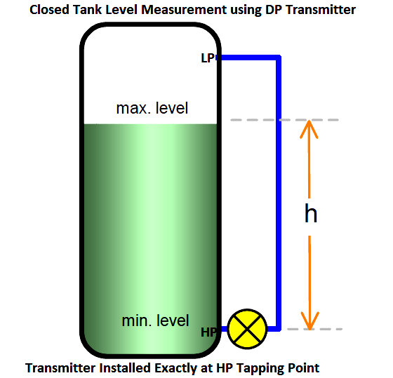
 Level Measurement using DP TransmittersWith wet leg ;

Span = ρp • g • H , or, = SGp • h

With dry leg ;

Span = ρp • g • H , or, = SGp • h

Transmitter mounted above the min. level
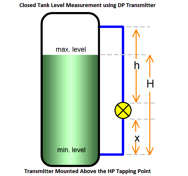
Closed Tank Level Measurement using DP Transmitter Installed Aove HP tapping PointClosed Tank Level Measurement using DP Transmitter Installed Aove HP tapping Point

With wet leg ;

Zero Elevation = − (ρf • g • x)

Span = ρp • g • H

With dry leg ;

Not preferable

Therefore, for calibration;

4mA (LRV) = Min. Head + Zero Elevation

20mA (URV) = Span + Zero Elevation

Transmitter mounted below the HP tap ;

Closed Tank Level Measurement using DP Transmitter Installed Below HP tapping Point

With dry leg ;

Pw at min. level = (SGf • x)

Pw at max. level = (SGf • x) + (SGp • H)

Span = SGp • H

With wet leg ;

Zero Suppression = − (ρf • g • h) ,or, = − (SGf • h)

Span = ρp • g • H , or, = SGp • H

Therefore, for calibration;

4mA (0%) = Zero Elevation

20mA (100%) = Span+Zero Suppression

Transmitter mounted below HP tapping point  & Minimum Level is Elevated
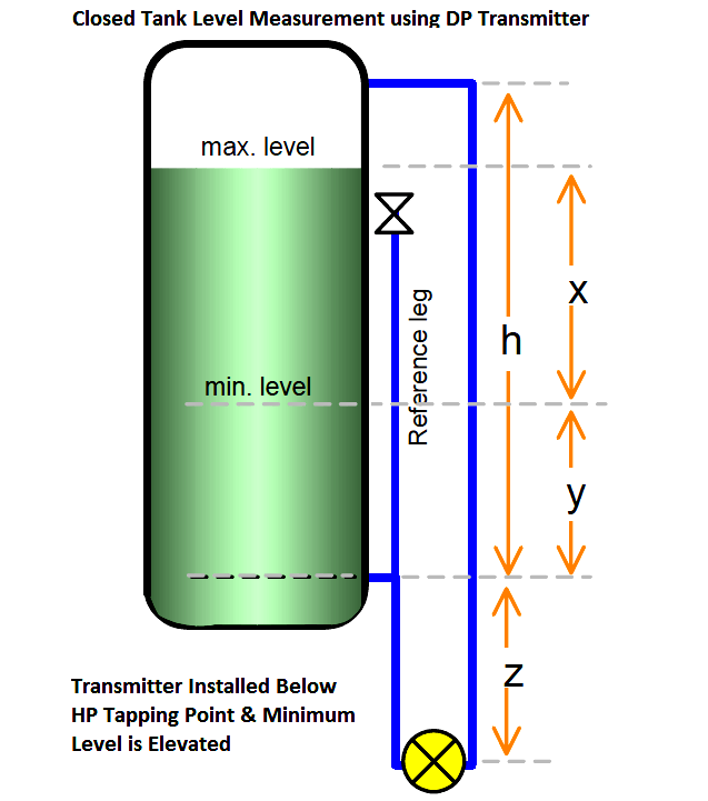
Closed Tank Level Measurement using DP Transmitter Elevated Minimum Level

With wet leg ;

Pw min = (SGp • y) − (SGf • d)

Pw max = (SGp)(x + y) − (SGf • d)

Span = ρp • g • x , or = SGp • x

With dry leg ;

Pw at min. level = (SGf • z) + (SGp • y)

Pw at max. level = (SGf • z) + (SGp)(x+y)

Span = SGp • H

NOTE:

ρp = density of process liquid in the tank
ρf = density of fill-liquid in the tubing
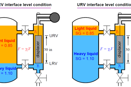
ρu = density of upper liquid
ρl = density of lower liquid
SGp = std. gravity of process liquid.
SGf = std. gravity of fill liquid
SGu = std. gravity of upper liquid
SGl = std. gravity of lower liquid
Pw = equivalent head of water

Article Source : N. Asyiddin

Don't Miss Our Updates
Be the first to get exclusive content straight to your email.
We promise not to spam you. You can unsubscribe at any time.
Invalid email address
You've successfully subscribed !

Continue Reading

Nuclear Interface Level Measurement Principle, Limitations, Installation and Calibration
Ultrasonic Level Transmitter Animation
Types of Level Measurement
What is Reflex Level Gauge?
DP Level Transmitter Elevation and Suppression Corrections
Displacer Level Sensor Working Animation
Share This Article
Facebook Whatsapp Whatsapp LinkedIn Copy Link
Share
4 Comments
  • Noor says:
    August 10, 2017 at 3:43 am

    If SG in close tank is fickle, sometime the value of SG is 0,8 and sometime 0.9, do we have to use wet leg or dry leg??

    Reply
  • jairo francisco says:
    October 7, 2017 at 1:03 am

    Muito show! Translated : Great!

    Reply
  • RAJATHIRAJAN BOKKAI says:
    October 20, 2019 at 1:57 pm

    Got good guidelines on how to fix the mounting position of the Level transmitter

    Reply
  • m says:
    September 27, 2023 at 12:46 pm

    Great Guide ! thank you

    Reply

Leave a Reply Cancel reply

Your email address will not be published. Required fields are marked *

Stay Connected

128.3kFollowersLike
69.1kFollowersFollow
210kSubscribersSubscribe
38kFollowersFollow

Categories

Explore More

Level Transmitter Animation
What is Thermal Differential Level Measurement?
Effects of Symmetric and Asymmetric Capillary Tube Pressure Measurement
Radar Tank Gauging
Questions on Level Switches
Ultrasonic Level Measurement Questions and Answers
Tilt Level Switch Working Principle
DP Transmitter Dry Leg & Wet Leg Calculations

Keep Learning

Hydrostatic pressure Measurement

Basics of Hydrostatic Level Measurement

Differential Pressure Transmitter Wet Leg Compensation

Differential Pressure Transmitters Compensated Leg Systems

Level Gauge Theory

Types of Level Gauges

electromechanical-level-measurement-working-principle

ElectroMechanical Level Measurement Working Principle

Displacer Level Transmitter Calibration Procedure

Displacer Level Transmitter Calibration using Water & Process Liquid

Wet Leg Level Transmitter

Basics of DP Level Measurement

The 5 ways Ultrasonic Sensors Work

The 5 ways Ultrasonic Sensors Work

How Buoyant Force instruments Works

How Buoyant Force instruments Works ?

Learn More

Problem in Water Level Control System

Problem in Water Level Control System

Types of active transducers

Types of Transducers in Instrumentation

Impulse Line Problems

What are Impulse Lines? – Impulse Line Problems & Solutions

BACNet Protocol

What is the BACNet Protocol? BACNet IP vs. BACNet MS/TP

Block Diagram

Block Diagram

PLC IO Examples

Quiz: Identifying I/O Examples in PLC Systems

Compressor IP Case Discharge Temperature Gradually Increases

Compressor Anti-Surge Control near-miss incident

Unstable & Drifting Values of Differential Pressure Transmitter

Unstable & Drifting Values of Differential Pressure Transmitter Problem

Menu

  • About
  • Privacy Policy
  • Copyright

Quick Links

  • Learn PLC
  • Helping Hand
  • Part Time Job

YouTube Subscribe

Follow US
All rights reserved. Reproduction in whole or in part without written permission is prohibited.
Welcome Back!

Sign in to your account

Username or Email Address
Password

Lost your password?