Inst ToolsInst ToolsInst Tools
  • Courses
  • Automation
    • PLC
    • Control System
    • Safety System
    • Communication
    • Fire & Gas System
  • Instrumentation
    • Design
    • Pressure
    • Temperature
    • Flow
    • Level
    • Vibration
    • Analyzer
    • Control Valve
    • Switch
    • Calibration
    • Erection & Commissioning
  • Interview
    • Instrumentation
    • Electrical
    • Electronics
    • Practical
  • Q&A
    • Instrumentation
    • Control System
    • Electrical
    • Electronics
    • Analog Electronics
    • Digital Electronics
    • Power Electronics
    • Microprocessor
  • Request
Search
  • Books
  • Software
  • Projects
  • Process
  • Tools
  • Basics
  • Formula
  • Power Plant
  • Root Cause Analysis
  • Electrical Basics
  • Animation
  • Standards
  • 4-20 mA Course
  • Siemens PLC Course
Reading: Centrifugal Compressor near ½-RPM Frequency High Magnitude Shaft Vibrations
Share
Font ResizerAa
Inst ToolsInst Tools
Font ResizerAa
  • Courses
  • Design
  • PLC
  • Interview
  • Control System
Search
  • Courses
  • Automation
    • PLC
    • Control System
    • Safety System
    • Communication
    • Fire & Gas System
  • Instrumentation
    • Design
    • Pressure
    • Temperature
    • Flow
    • Level
    • Vibration
    • Analyzer
    • Control Valve
    • Switch
    • Calibration
    • Erection & Commissioning
  • Interview
    • Instrumentation
    • Electrical
    • Electronics
    • Practical
  • Q&A
    • Instrumentation
    • Control System
    • Electrical
    • Electronics
    • Analog Electronics
    • Digital Electronics
    • Power Electronics
    • Microprocessor
  • Request
Follow US
All rights reserved. Reproduction in whole or in part without written permission is prohibited.
Inst Tools > Blog > Root Cause Analysis (RCA) > Centrifugal Compressor near ½-RPM Frequency High Magnitude Shaft Vibrations

Centrifugal Compressor near ½-RPM Frequency High Magnitude Shaft Vibrations

Root Cause Analysis (RCA): Compressor near ½-RPM frequency high magnitude shaft vibrations.

Last updated: September 28, 2022 3:20 pm
S Raghava Chari
Root Cause Analysis (RCA) Process
No Comments
Share
2 Min Read
SHARE

Root Cause Analysis (RCA): Compressor near ½-RPM frequency high magnitude shaft vibrations.

Contents
Centrifugal Compressor Shaft Vibrations ProblemSolution
Article Type:Root Cause Analysis (RCA)
Category:Mechanical
Equipment Type:High Speed, Hi KW Major Rotating Machines
Author:S. Raghava Chari

Note: This root cause analysis (RCA) is from real-time scenarios that happened in industries during the tenure of one or two decades ago. These articles will help you to improve your troubleshooting skills and knowledge.

Centrifugal Compressor Shaft Vibrations Problem

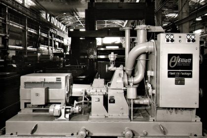
K-603, a horizontally split 8000 RPM, 2000 KW, centrifugal compressor draws 300 mm WC CO2 and delivers it at 13-bars. It performed fine, but for 45 to 50% x shaft RPM frequency 75 to 100 microns amplitude high shaft vibration problems.

Unable to find a cause, the plant lived with high vibration problems for over 5 years.

Solution

The author learnt from a tech journal article that tilting pad bearings eliminated such vibration problems in a compressor.

Substituting compressor vendor-supplied TPB was the answer.

Author: S. Raghava Chari

Do you face any similar issues? Share with us through the below comments section.

If you liked this article, then please subscribe to our YouTube Channel for Instrumentation, Electrical, PLC, and SCADA video tutorials.

You can also follow us on Facebook and Twitter to receive daily updates.

Read Next:

  • Process Air Compressor Overhauls
  • Heat Exchanger Root Cause Analysis
  • Mechanical Variable Speed Drives RCA
  • Compressor Case Discharge Temperature
  • TEFC Motors Rampant Winding Burnouts
Don't Miss Our Updates
Be the first to get exclusive content straight to your email.
We promise not to spam you. You can unsubscribe at any time.
Invalid email address
You've successfully subscribed !

Continue Reading

Introduction to Wastewater Treatment Works and Pumping Station
Rupture Discs bursts caused too many Urea Plant Shutdowns
Repeat Control Valve Plug Stem and Gland Leaks
Fan Motor Frequent Journal Bearing Failures Posed Plant Outages
Gas Compressor Seal Oil System
Bellows Steam Trap
Share This Article
Facebook Whatsapp Whatsapp LinkedIn Copy Link
Share
Leave a Comment

Leave a Reply Cancel reply

Your email address will not be published. Required fields are marked *

Stay Connected

128.3kFollowersLike
69.1kFollowersFollow
210kSubscribersSubscribe
38kFollowersFollow

Categories

Explore More

Oil and Gas Interview Questions Answers
Gearbox within week Failing Journal Bearing upset Plant Operations
Under and Over-Capacity Control Valve Pose Poor Controllability
Failing Weigh Feeders and Mechanical Variable Speed Drives (VSD)
Leaking Plug Valves Pose Safety Hazards and Lead to Plant Shutdown
Phosphate Dozing System Problems
Incident Investigation: Motor Operated Valve Lesson
Process Air Compressor too Frequent & too Lengthy Overhauls Eliminated

Keep Learning

Burst Transformers Root Cause Analysis

Root Cause Analysis – Burst Transformers and 11 kV Input Breakers

11 KV Bus A to Bus B Phase Check Problem

11 KV Bus A to Bus B Phase Check Problem

Rotary Granulator Drive

Rotary Granulator Drive Root Cause Analysis (RCA)

Failed Letdown Valve

Failed Letdown Valve Shuts down a Urea Plant Several Hours

Innovative Segment Orifice

Pitot-tube Replaced with Innovative Segment Orifice Plate

What is Hot Water Recirculation Loop

What is Hot Water Recirculation Loop? Advantages & Design

Plunger Pump

Within Few Weeks Failing Acid Dozing Pumps

repairs of welding cast refractory lined box over the hot spots

Too often done riskily repaired Roof Hot Spots eliminated forever

Learn More

Image Processing Projects for Engineering Students

Image Processing Projects for Engineering Students

calibrating-and-testing-rtd-sensors

RTD Calibration Procedure

Difference Between Metering CT and Protection CT

Difference Between Metering CT and Protection CT

Power Electronics Objective Questions

Dual Converters Objective Questions

Conductive Level Switch Principle

Conductive Level Switch Principle

Digital Electronics Multiple Choice Questions

Counters Objective Questions

Motor Control Center Purpose

Motor Control Center – Purpose, Classification, and Advantages

Basic components of a Thermowell

What is Thermowell and How-to choose Thermowell Probe Length ?

Menu

  • About
  • Privacy Policy
  • Copyright

Quick Links

  • Learn PLC
  • Helping Hand
  • Part Time Job

YouTube Subscribe

Follow US
All rights reserved. Reproduction in whole or in part without written permission is prohibited.
Welcome Back!

Sign in to your account

Username or Email Address
Password

Lost your password?