Explain the operation of this cascade temperature control system:
Cascade Temperature Control System

Cascade control systems (also called two-element control systems) have two control “loops” functioning: a master and a slave (also known as primary and secondary, respectively). Identify the master (primary) and slave (secondary) loops in this temperature control system, and also determine which loop should be tuned first (and why!).
Also, identify the appropriate controller actions for each loop, assuming direct-acting transmitters and an air-to-open valve. Annotate this diagram with “+” and “−” symbols showing the influences PV and SP have on each controller, and explain how these symbols help your analysis of the controllers’ actions.
Answer:
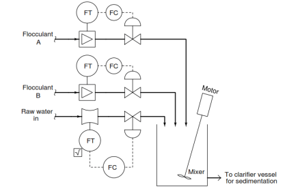
The temperature controller (TC) provides a “remote” setpoint to the flow controller (FC), which throttles the flow control valve (FV) to achieve the desired rate of steam flow.
Master (primary) = Reactor temperature
Slave (secondary) = Steam flow
When tuning cascaded loops, you should always ensure the slave loop is well-tuned before attempting to tune the master loop. I’ll let you figure out why this is important!

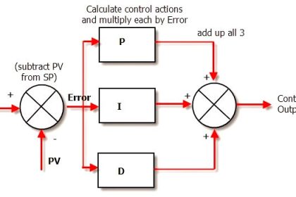
A useful problem-solving strategy for determining necessary controller actions in a cascade control system is to replace the ISA-standard “bubble” symbols for controllers with triangular opamp symbols, complete with “+” and “−” symbols at the inputs.
One input of each “opamp” controller will be the PV, while the other input of each “opamp” controller will be the SP. The inverting and noninverting inputs standard to all operational amplifiers helps remind you that the PV and SP inputs of a loop controller always have opposite effects on the output signal.
So a helpful strategy for identifying necessary master and slave controller actions in a cascade control system is to re-draw the controller “bubbles” as opamp symbols instead, complete with “+” and “−” labels for noninverting and inverting inputs, respectively.
Since all PID controllers have PV and SP inputs, and these inputs always have opposite effects on the output signal, the opamp conventions of “+” and “−” work very well to describe the action of any PID controller. If the PV input on the opamp controller must be noninverting (“+”) in order to achieve loop stability, then that controller must be direct-acting.
If the PV input on the opamp controller must be inverting (“−”) in order to achieve loop stability, then that controller must be reverse-acting.
The following diagram shows how to use opamp symbols to represent controller actions in the same cascaded flow/temperature control system:

Note that it is always the inputs of a controller we label with “+” or “−” symbols, never the output of a controller.
Questions for you:
When tuning each loop controller (TIC, FIC), what should be done with the other controller? Should the other controller be in automatic mode or manual mode, and why?
Suppose the control valve were switched from air-to-open to air-to-close. Would both master and slave controller actions need to be reversed, or just one of the controllers? If just one, which one?
Identify any load(s) on this process that are not being corrected or otherwise compensated for by cascade control.
Share Your Answers with us through comments.
Read Next:
- Control Valve Split Range Loop
- Industrial Automation and Control
- PID Controllers Graphical Analysis
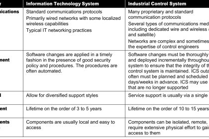
- Security of Automation Systems
- Pressure Control Problems
Credits: Tony R. Kuphaldt