Inst ToolsInst ToolsInst Tools
  • Courses
  • Automation
    • PLC
    • Control System
    • Safety System
    • Communication
    • Fire & Gas System
  • Instrumentation
    • Design
    • Pressure
    • Temperature
    • Flow
    • Level
    • Vibration
    • Analyzer
    • Control Valve
    • Switch
    • Calibration
    • Erection & Commissioning
  • Interview
    • Instrumentation
    • Electrical
    • Electronics
    • Practical
  • Q&A
    • Instrumentation
    • Control System
    • Electrical
    • Electronics
    • Analog Electronics
    • Digital Electronics
    • Power Electronics
    • Microprocessor
  • Request
Search
  • Books
  • Software
  • Projects
  • Process
  • Tools
  • Basics
  • Formula
  • Power Plant
  • Root Cause Analysis
  • Electrical Basics
  • Animation
  • Standards
  • 4-20 mA Course
  • Siemens PLC Course
Reading: Calculate Process Variable from 4-20mA using Fraction of Measurement
Share
Font ResizerAa
Inst ToolsInst Tools
Font ResizerAa
  • Courses
  • Design
  • PLC
  • Interview
  • Control System
Search
  • Courses
  • Automation
    • PLC
    • Control System
    • Safety System
    • Communication
    • Fire & Gas System
  • Instrumentation
    • Design
    • Pressure
    • Temperature
    • Flow
    • Level
    • Vibration
    • Analyzer
    • Control Valve
    • Switch
    • Calibration
    • Erection & Commissioning
  • Interview
    • Instrumentation
    • Electrical
    • Electronics
    • Practical
  • Q&A
    • Instrumentation
    • Control System
    • Electrical
    • Electronics
    • Analog Electronics
    • Digital Electronics
    • Power Electronics
    • Microprocessor
  • Request
Follow US
All rights reserved. Reproduction in whole or in part without written permission is prohibited.
Inst Tools > Blog > Formulas > Calculate Process Variable from 4-20mA using Fraction of Measurement

Calculate Process Variable from 4-20mA using Fraction of Measurement

Last updated: July 25, 2019 3:29 pm
Editorial Staff
Formulas
1 Comment
Share
1 Min Read
SHARE

An electronic transmitter with an output of 4 – 20 mA is calibrated for a pressure range of 7 – 10 MPa(g). What pressure is represented by a 12 mA signal?

Solution

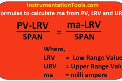
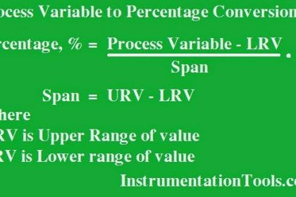
Signal Span or Span of transmitter 20 mA – 4 mA = 16 mA

Output Signal = 12 mA

Live Zero = 4 mA

Base Point = LRV of Range = 7

Process Span = URV -LRV = 10 – 7 = 3

Calculate Process Variable from 4-20mA using Fraction of Measurement

Fraction of Measurement Change = 12 – 4 / 16  = 0.5

Actual Process Change = (Fractional Change) x (Process Span)

Actual Process Change = 0.5 x (10 – 7 MPa) = 1.5 MPa

Actual Process Value   = Base Point + Process Change

Actual Process Value = 7 + 1.5 MPa = 8.5 MPa(g)

Result :

Pressure at 12 mA is 8.5 MPag

Articles You May Like :

4–20 mA Process Control Loops

Pressure Transmitter Troubleshooting

Basics of Loop Checks

Instrument Calibration MCQ

Gas Flow Formulas

Don't Miss Our Updates
Be the first to get exclusive content straight to your email.
We promise not to spam you. You can unsubscribe at any time.
Invalid email address
You've successfully subscribed !

Continue Reading

Turbine Flow Meter Coefficient and Scaling Factor
Formula for Process Variable to Percentage Conversion
Formula for Percentage to Process Variable Conversion
Gas Flow Formulas
PLC Problems Troubleshooting
How to do 4-20mA Conversions Easily
Share This Article
Facebook Whatsapp Whatsapp LinkedIn Copy Link
Share
1 Comment
  • Muneer Choglay says:
    November 19, 2017 at 10:39 am

    This is one of the very beautiful website i have ever come across. Thank you so much Sir. S. B. Reddy for your great efforts and dedication. Thanks for this gift of knowledge.

    Reply

Leave a Reply Cancel reply

Your email address will not be published. Required fields are marked *

Stay Connected

128.3kFollowersLike
69.1kFollowersFollow
210kSubscribersSubscribe
38kFollowersFollow

Categories

Explore More

Input-Output Relationships of Transmitters
DP Transmitter Dry Leg & Wet Leg Calculations
Calculate Control Valve Stem Position
Calculate Temperature Coefficient of RTD
Siemens Differential Pressure Transmitter Calculations (Flange Type)
Instrument Percent of Span Error
Instrumentation Basics – Range Conversion Formula and Examples
Calculate Flow Transmitter Output Current

Keep Learning

Closed Tank Remote Seal Level Transmitter calculation

Remote Seal Transmitters Ranging Calculation

Process variable to 4-20mA Conversion

Formula to Calculate 4-20 mA from Process Variable

How to Convert Cable Size from AWG to Inches

How to Convert Cable Size from AWG to Inches

Capillary Remote Seal Leave Measurement

Siemens Pressure Transmitter with Remote Seals Calculations

Zero Suppression in level Measurement

Zero Suppression and Zero Elevation Calculations

4-20 mA Conversion Formulas

Standard 4 to 20 mA Conversion Formula

Field Transmitter Range Calculation

Transmitter Turndown Ratio, Set Span and Zero Span

Level Calculation with Remote Seals

Level Calculation with Remote Seals

Learn More

Configuration of Siemens Scada and PLC

#12 PLC Best Practices – Validate Inputs based on Physical Plausibility

Instrumentation Project Engineers Interview Questions

Instrumentation Project Engineer Interview Questions

Dall Tube Flow Meter Working Principle

Dall Tube Flow Meter – Principle, Advantages, Disadvantages

PLC Latching circuit Animation

What is Seal-in Circuit ?

How to Identify the Transistor Terminals

Electrical Machines Questions and Answers

Induction Machines Circle Diagrams

Bipolar Junction Transistor Construction

Bipolar Junction Transistor Construction

Stilling well in liquid level measurement

Stilling Well in Interface Level Measurement System

Menu

  • About
  • Privacy Policy
  • Copyright

Quick Links

  • Learn PLC
  • Helping Hand
  • Part Time Job

YouTube Subscribe

Follow US
All rights reserved. Reproduction in whole or in part without written permission is prohibited.
Welcome Back!

Sign in to your account

Username or Email Address
Password

Lost your password?