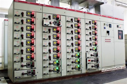
Root Cause Analysis (RCA): An 11000/400V transformer and its 11 kV input breaker burst on an occasion and an 11/3.3KV transformer only on another.
Note: This root cause analysis (RCA) is from real-time scenarios that happened in industries during the tenure of one or two decades ago. These articles will help you to improve your troubleshooting skills and knowledge.
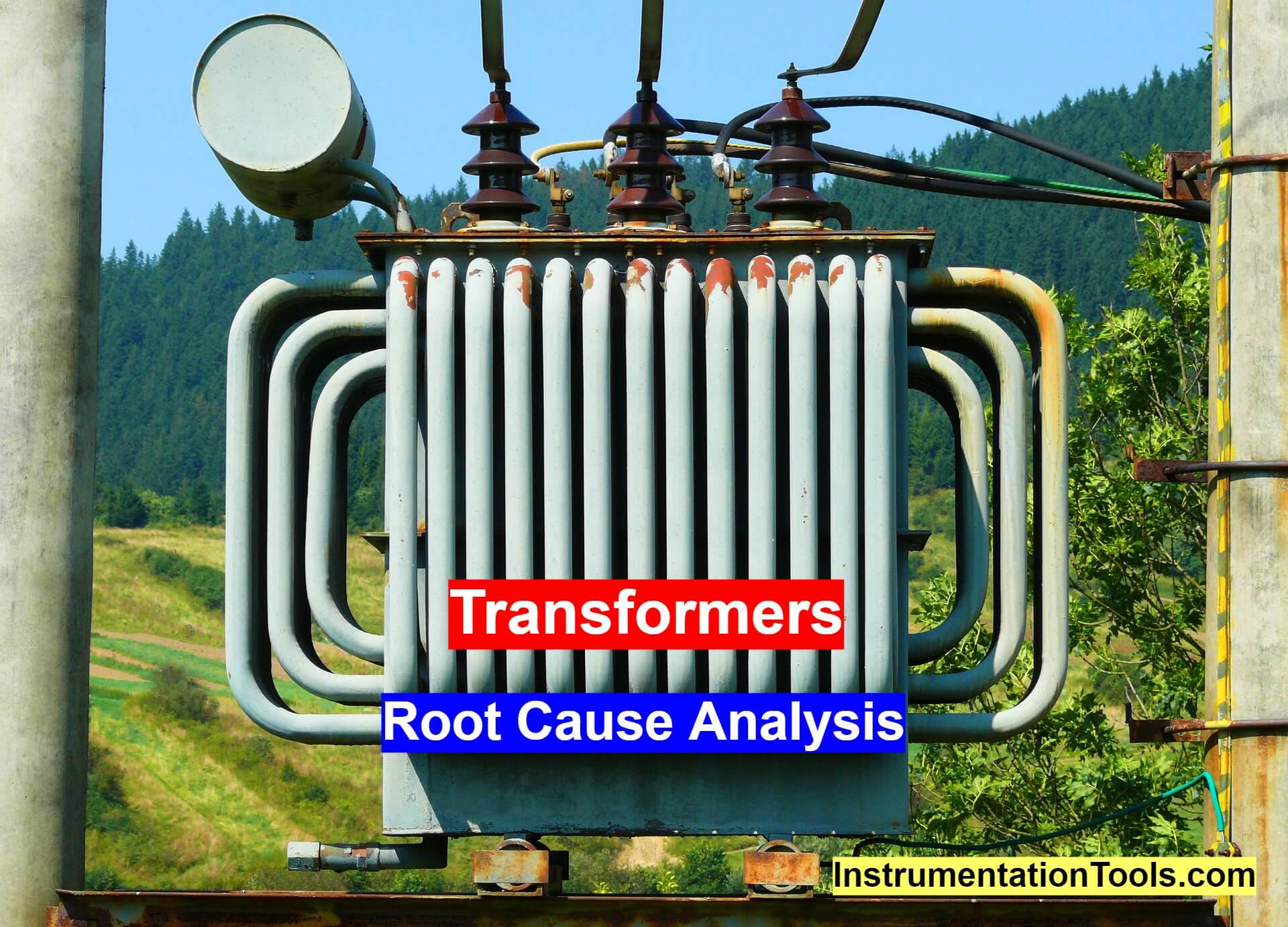
Burst Transformers Root Cause Analysis
Electrical Systems Insulation Resistance (IR) falling below the thumb rule 1 MΩ / kV because of the plant’s corrosive emissions and system flashes were common in that plant.
The author tipped by a US journal ad purchased the advertised Silicone Compound 800 kg, cleaned well all indoors and outdoors 110 kV, 11 kV, 3.3kV, and 400 V electrical systems insulators and 3-mm thick SC coated.
Maybe one such low IR – before the SC era – caused several times the rated load current fault currents and the unreliable breaker not tripping on protection relay command burst; the connected transformer also burst.
The second case is analogous to the first but the transformer only burst and fortunately the breaker survived.
Author: S. Raghava Chari
Do you face any similar issues? Share with us through the below comments section.
If you liked this article, then please subscribe to our YouTube Channel for Instrumentation, Electrical, PLC, and SCADA video tutorials.
You can also follow us on Facebook and Twitter to receive daily updates.
Read Next: