Inst ToolsInst ToolsInst Tools
  • Ask
  • Courses
  • Videos
  • Q & A
    • Interview
      • Instrumentation
      • Electronics
      • Electrical
      • Practical Questions
    • MCQ
      • Instrumentation MCQ
      • Electrical MCQ
      • Electronics MCQ
      • Control Systems MCQ
      • Analog Electronics MCQ
      • Digital Electronics MCQ
      • Power Electronics MCQ
      • Microprocessor MCQ
      • Multiple Choice Questions
  • EE
    • Electronics
      • Electronics Q & A
      • Electronic Basics
      • Electronic Devices & Circuits
      • Electronics Animation
      • Digital Electronics
    • Electrical
      • Electrical Basics
      • Electrical Q & A
      • Power Electronics
      • Electrical Machines
      • Electrical Animation
      • Power Systems
      • Switchgear & Protection
      • Transmission & Distribution
  • Measure
    • Control Valves
    • Calibration
    • Temperature
    • Pressure
    • Flow
    • Level
    • Analyzers
    • Switches
    • Vibration
    • Solenoid Valve
  • Control
    • PLC Tutorials
    • Control Systems
    • Safety Instrumented System (SIS)
    • Communication
    • Fire & Gas System
  • More
    • Design
    • Tools
    • Animation
    • Basics
    • Formulas
    • Standards
    • TextBooks
    • Common
    • Software
    • Excel Tools
    • Erection & Commissioning
    • Process Fundamentals
    • Videos
    • Books
Search
All rights reserved. Reproduction in whole or in part without written permission is prohibited.
Reading: Burner Safety Logic for Initial Lighting
Share
Notification Show More
Font ResizerAa
Inst ToolsInst Tools
Font ResizerAa
  • Courses
  • PLC Tutorials
  • Control Systems
Search
  • Ask
  • Courses
  • Videos
  • Q & A
    • Interview
    • MCQ
  • EE
    • Electronics
    • Electrical
  • Measure
    • Control Valves
    • Calibration
    • Temperature
    • Pressure
    • Flow
    • Level
    • Analyzers
    • Switches
    • Vibration
    • Solenoid Valve
  • Control
    • PLC Tutorials
    • Control Systems
    • Safety Instrumented System (SIS)
    • Communication
    • Fire & Gas System
  • More
    • Design
    • Tools
    • Animation
    • Basics
    • Formulas
    • Standards
    • TextBooks
    • Common
    • Software
    • Excel Tools
    • Erection & Commissioning
    • Process Fundamentals
    • Videos
    • Books
Follow US
All rights reserved. Reproduction in whole or in part without written permission is prohibited.
Inst Tools > Blog > Control Systems > Burner Safety Logic for Initial Lighting

Burner Safety Logic for Initial Lighting

Last updated: April 18, 2020 12:56 pm
Editorial Staff
Control Systems
No Comments
Share
5 Min Read
SHARE

In this article we will go throw some Standard burner safety logic for initial lighting of the burner and also we are going to implement these logics in ladder format using SUPCON DCS system ECS700 Series.

Contents
What is a Burner?Why we require safety for the burner?Industrial burner:Safety LogicsPurging Cycle:Burner SafetyRead Next:

What is a Burner?

A Mechanical device that performs lean combustion between 2 or more fuels in a controlled manner is called as the burner.

Why we require safety for the burner?

Burners present fire hazards. They produce a flame and burn at a high temperature in the furnace and as a result, there is potential for an accident to occur.

Industrial burner:

The Industrial burner has covered about half of the market and is growing rapidly.

Below are some good advantage of burners to overcome the traditional firing of the boiler.

  • Efficiency up to 80-95%
  • Proper fuel combustion
  • Low emission from chimney.
  • Only single operator can operate the single boiler
  • Low service cost

Safety Logics

  • ESS (Emergency Stop Switch) should not be pressed.

The ESS is a switch provided for a boiler operator on the control panel to stop the burner in the Emergency condition.

  • ID & FD fan should be not be in running condition.

When you are initially firing a burner the heavy motor used in boiler should not be in ON state.

  • Fuel Line Pressure Should be OK

Suppose we want to burn biogas the pressure of biogas line as assigned should be 350mBar. These signal will be provided by the pressure switch.

  • Biogas Control valve should be closed
  • Biogas SOV (Solenoid valve) should be close
  • FD fan damper should be closed
  • Steam drum level should be ok (50%)
  • Flame not present in furnace.

The flame scanner is provided for burner safety and feedback whether flame in furnace is present or not.

Also Read: Burner Management System Interlock

Now if all the above safety logics are satisfied then the burner will enable its start button for boiler operator. And after that, the purging cycle will start.

Burner Safety Logic

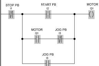
Figure (a): Burner Safety Logic

Purging Cycle:

It is nothing but the clearing of the entire flue gas path for any combustibles that are leftover in the furnace. This cycle is performed by FD fan and ID fan.

Burner Purging Cycle Logic

Figure (b) Purging cycle.

As per the program in fig (a) if any of the condition during the purging cycle fails then we need to reset the burner manually through the HMI and again start the burner.

Burner Control Loop Graphics

Burner Start Stop Sequence

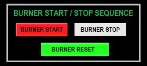
Figure (c) shows that during purging we got a DI signal from flame Scanner.

Now successfully when we complete the purging cycle the burner is ready for firing.

Burner Safety

In this topic, we will go through the process after starting the burner and how the steam is generated in the boiler along with the flow diagram fig (d)
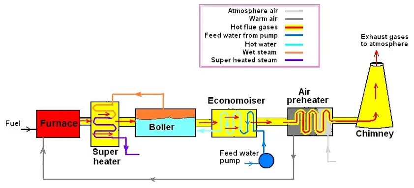
Flue Gas Path in Burner

Figure (d)

Air and Gas Flow in Burner

When the burner gets to start with all the safeties interlock of boiler and burner itself. The natural circulation of water started as the steam generation takes place.

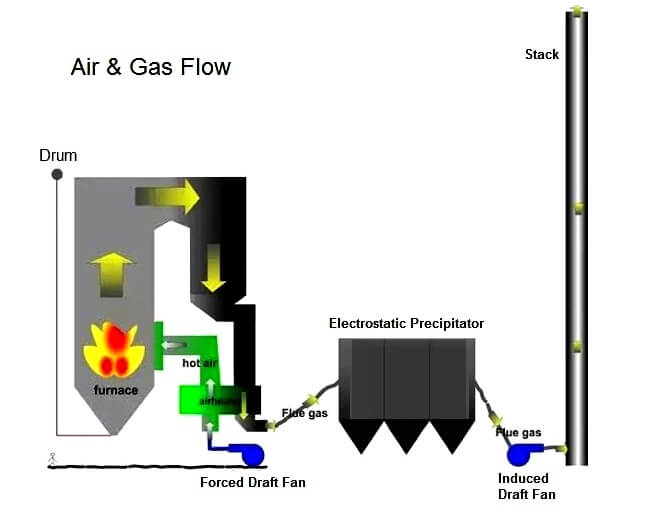
The flue gas from the furnace passes through the superheater, economizer, ESP and last to the duct of the chimney. The flow diagram in figure (e).
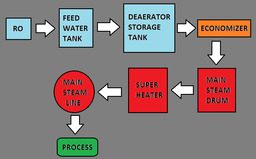
Boiler Process Flow Diagram

Figure (e)

The water from the RO plant is stored in the feed water tanks, then the water flows to deaerator to economizer the let water to flow into the steam drum and after that, the steam goes through superheater and at last the main steam line which is utilized by the customer as per its process.

Author: Amit Jadhav

Read Next:

  • Turbine Supervisory Instrumentation
  • PLC on Industrial Automation
  • Blast Furnace Panel Modification
  • Why choose Intrinsic Safety?
  • Gas Turbine Questions
Don't Miss Our Updates
Be the first to get exclusive content straight to your email.
We promise not to spam you. You can unsubscribe at any time.
Invalid email address
You've successfully subscribed !
Augmented Reality and Virtual Reality in Industrial Automation
Process Dynamics and PID Controller Tuning
Chemical Reactor Temperature Control System
Tuning a Liquid Level Process Control Loop
Introduction to PlantPAx Distributed Control System
Share This Article
Facebook Whatsapp Whatsapp LinkedIn Copy Link
Share
Leave a Comment

Leave a Reply Cancel reply

Your email address will not be published. Required fields are marked *

Stay Connected

128.3kFollowersLike
69.1kFollowersFollow
208kSubscribersSubscribe
38kFollowersFollow

Categories

Recent Comments

  • Kamli on Top Free PLC Software
  • Guifty Shimica on Top Non-PLC Certification Courses for Automation Professionals
  • Guifty Shimica on Top Non-PLC Certification Courses for Automation Professionals
  • MIHARITSOA Aina Sitraka on Top Non-PLC Certification Courses for Automation Professionals

Related Articles

4-20mA Loop Power Supply Questions

4-20mA Loop Power Supply Questions and Answers

CAN Protocol with the OSI Model

Basics for CAN Bus Protocol – Controller Area Network

Modbus Function code 02 – Read Contact(s)

Modbus Function Command Formats

Alarm Chattering

Categorization of Alarms in a Process Plant

Grounding or Earthing Scheme in DCS or PLC Systems

Grounding or Earthing Scheme in DCS or PLC Systems

Basics of Motion Controllers

Basics of Motion Controllers

Types of Cables used in Industrial Automation

Types of Cables used in Industrial Automation

What is Static Grounding

What is Static Grounding?

More Articles

Automated Garage Gate Control - PLC Ladder Logic

Automated Garage Gate Control – PLC Ladder Logic

Industrial Flame Detectors

Industrial Flame Detectors

Mechanical Engineering Design and Fabrication Projects

300+ Mechanical Engineering Design and Fabrication Projects

Passing Control Valves Cause Yearly Losses

Passing Control Valves Cause Yearly Losses in Production Plant

Configuration of Siemens Scada and PLC

#12 PLC Best Practices – Validate Inputs based on Physical Plausibility

LVR Motor Controller Operation

Low Voltage Protection (LVP) and Low Voltage Release (LVR)

Digital Control Systems

Stability Analysis

Electrical Cabinet Air Conditioner

Electrical Cabinet Air Conditioner – Enclosure Cooling, Maintenance

Follow US
All rights reserved. Reproduction in whole or in part without written permission is prohibited.
Welcome Back!

Sign in to your account

Username or Email Address
Password

Lost your password?