This article teaches how to convert Boolean logic to PLC programming ladder logic with the video tutorial.
Note: The logic diagram example shown here is for educational use only for engineering students to understand PLC principles.
Boolean Logic to PLC
Problem Statement
Design a PLC ladder logic for the following Boolean Expression.
We are using toggle Inputs to control the output.
Convert the boolean logic to PLC logic.
Y = A’B
Video
The below video explains the boolean logic conversion with detailed steps.
Inputs
The required inputs mentioned below.
A: I0.0
B: I0.1
Outputs
The required outputs mentioned below.
Y: Q0.0
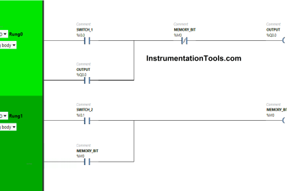
PLC Programming
The equivalent PLC programming is shown below.
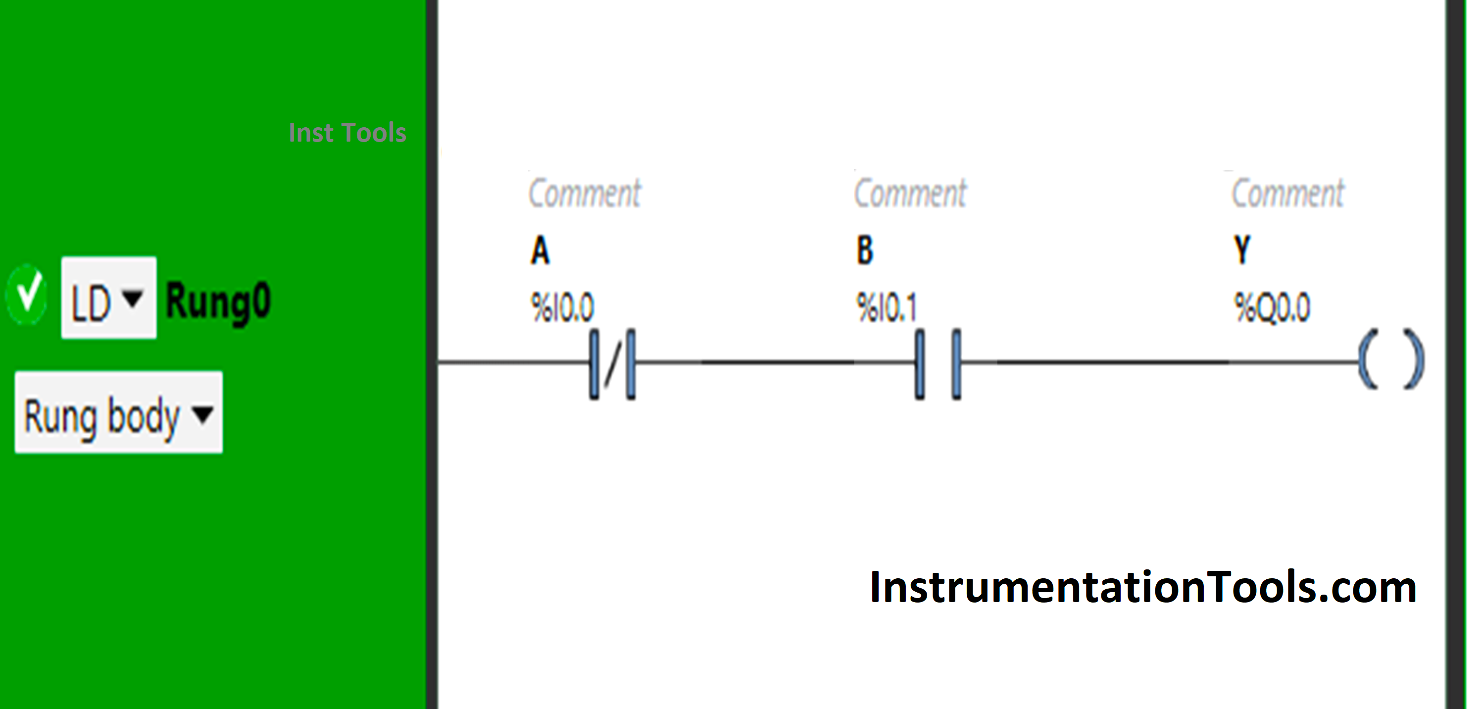
Program Description
- We used Schneider PLC programming software.
- In the above program, we have used Normally Closed Contact for Input A and Normally Open Contact for Input B.
- Normally Closed Contact is used for Input A, thus implementing NOT Logic Gate.
- For the output Y (Q0.0) to be ON, Input A should be OFF and Input B should be ON.
- Input A will only pass the signal when it is in a false state.
- Turning ON Input A will turn OFF Y(Q0.0) because Normally Closed Contact in the true state does not allow the signal to pass through it.
Result
When Input A is OFF and Input B is ON
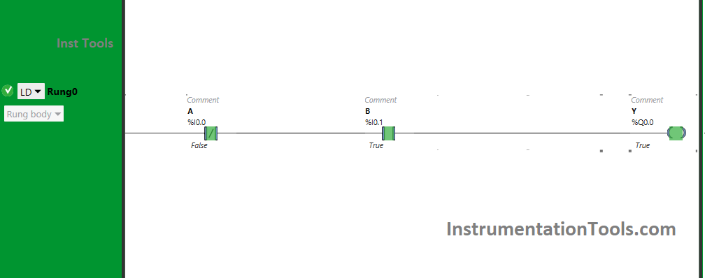
The signal will pass through Input A as Normally Closed Contact will pass the signal through it when in a false state. Also, Input B will pass the signal when in the true state because it is in Normally Open Contact, and Y(Q0.0) will turn ON.
When the input A is turned ON, as it is Normally Closed Contact, it will not allow the signal to pass. The state of Input B will not matter as the signal will not reach there when the input A is ON.
As a result, the output Y (Q0.0) will not turn ON. So, for the output Y (Q0.0) to be ON. The Input A should be OFF and the Input B should be ON.
If you liked this article, please subscribe to our YouTube Channel for PLC and SCADA video tutorials.
You can also follow us on Facebook and Twitter to receive daily updates.
Read Next:
- PLC Checksum Integrity Checks
- Programmable Logic Controller Test
- Operational Logic in the PLC Program
- Car Washing PLC Ladder Programming
- DCS in Industrial Automation Tutorials