The final outputs (functionalities) of each Industrial Process Plant Project can be observable in the actual safety and performances of the plant which are some reflections of implemented functionalities in the Control and Safety Systems of the project.
Systems Vendors for implementing required process functionalities (project requirements) at the Project Design Phase shall have close and exact coordination and communication with design I&C specialists for transferring and interchanging data and information relevant to project requirements and have the same understanding of them. On the other hand at the Plant Operation Phase, the end user specialists shall have good abilities in finding the systems implemented facilities and easily use them or accordingly communicate with them.
To reach such targets, systems vendors shall configure and program the systems by standard formats and routines to present good systems aspects. In this article, we will review generally some considerations in such approach.
Process Control and Safety Systems Functions
Each Industrial Project has some Process Plant Control & Safety Systems Aspects that may be reviewed generally in the reference article.
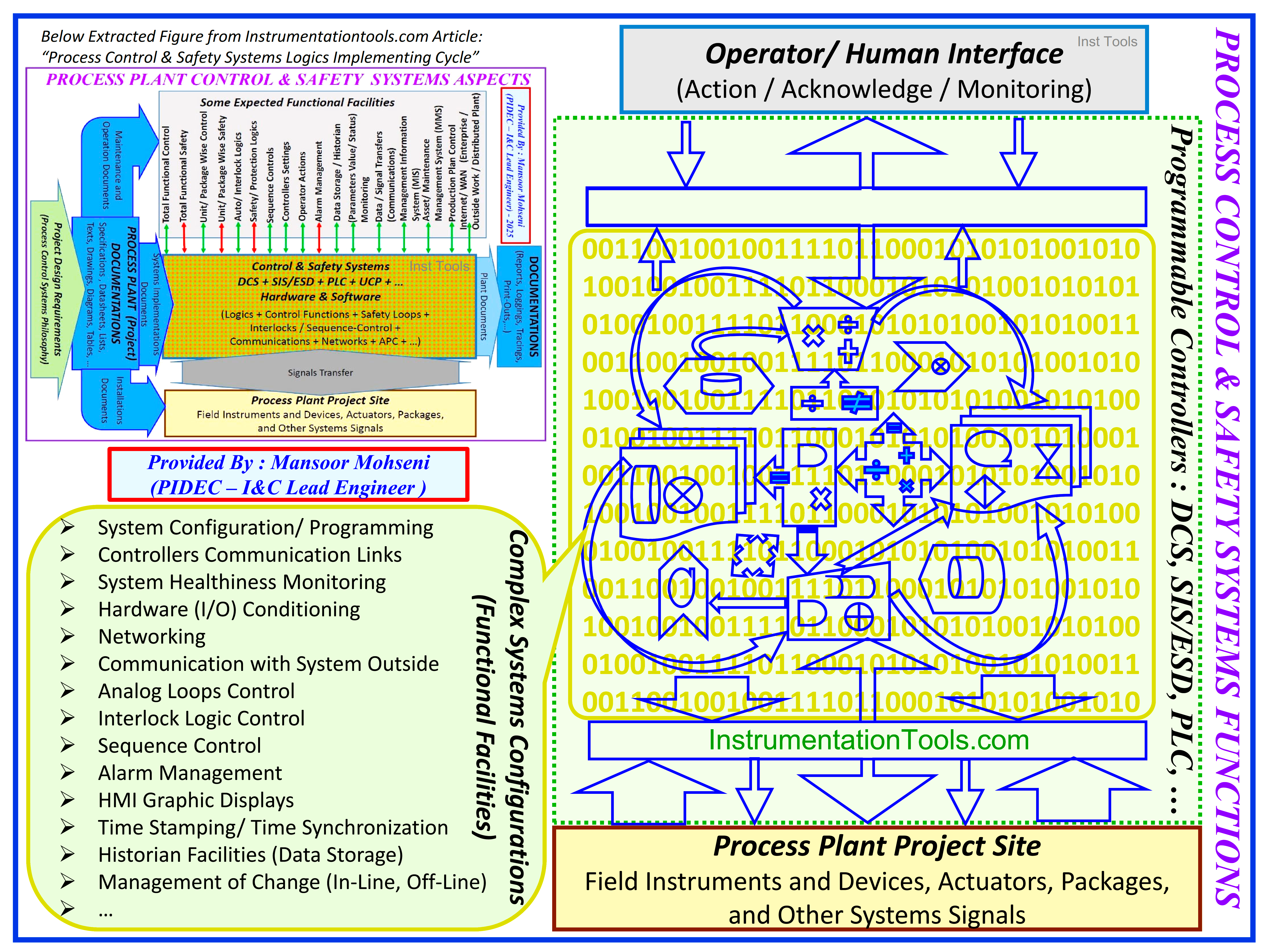
Figure-1: Process Control and Safety Systems Functions
Such aspects will be available by employing Programmable Control Systems in different formats and types such as Distributed/ Digital Control Systems (DCS), Safety Instrumented / Emergency Shut-Down Systems (SIS/ ESD), Programmable Logic Systems (PLC), etc.
As Figure-1 shows, execution parts of such systems may include some functional facilities to enable them to produce the required shown project aspects.
Functional Facilities
Some of such functional facilities may be listed as:
- System Configuration/ Programming
- Controllers Communication Links
- System Healthiness Monitoring
- Hardware (I/O) Conditioning
- Networking
- Communication with the System Outside
- Analog Loops Control
- Interlock Logic Control
- Sequence Control
- Alarm Management
- HMI Graphic Displays
- Time Stamping/ Time Synchronization
- Historian Facilities (Data Storage)
- Management of Change (In-Line, Off-Line) …
In fact, in order to match the above-mentioned facilities exactly based on Project Requirements, such systems need Configuration or Programming Language for setting and defining the available systems facilities. Nowadays different systems (or vendors) have their own (dedicated) language for their systems, while they follow some standard routines, formats, sequences, etc.
Following such standards makes their systems facilities easily understandable and usable/ configurable by specialists via some routine/ standard training and some more studies in their documents.
It is very important to know that based on project size and different required facilities (based on Project Process Control Systems Philosophy) the complexity of systems will differ and hence the configurations of such systems will differ. As much as the system’s complexity is greater, the need for using standards is greater. So following the famous known standards is the big advantage of systems vendors for selecting their systems for Process Plant Projects via responsible specialists. Considering this chance, causes approximately all vendors to follow such standards as mandatory.
IEC 61131-3 as Standard on Programming Languages of Programmable Controllers
The most famous standard that is used approximately by all system vendors is IEC-61131-3 which is standard on Programming Languages of Programmable Controllers (see Figure-2).
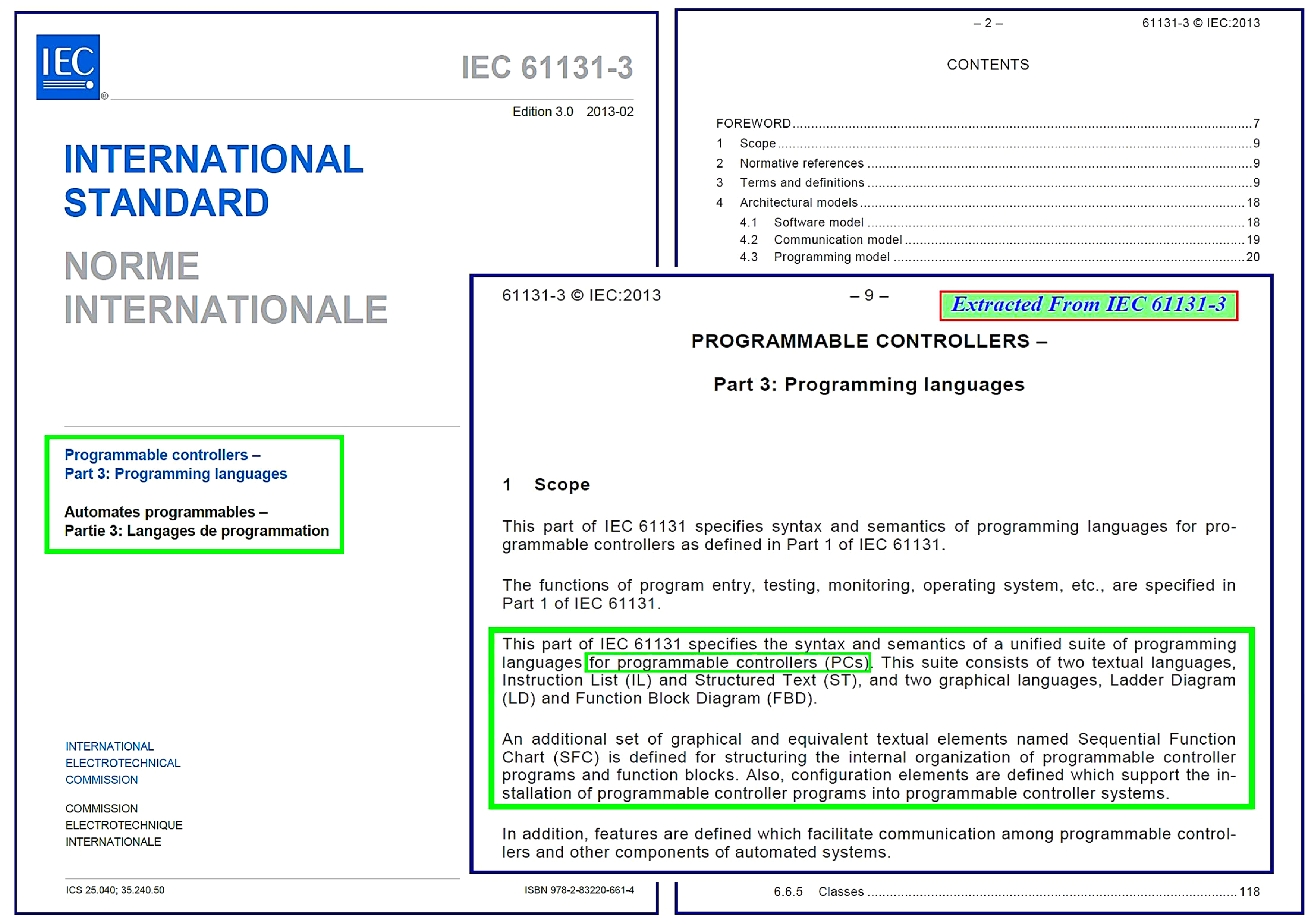
Figure-2: IEC 61131-3 as Standard on Programming Languages of Programmable Controllers
As Figure-2 shows this IEC 61131-3 standard explains the requirements and formats of five programming languages:
- Instruction List (IL),
- Structured Text (ST),
- Ladder Diagram (LD),
- Functional Block Diagram (FBD), and
- Sequential Function Chart (SFC).
Since nowadays most Process Control and Safety Systems are Programmable types, such standards may be known or referred to as standards for Automation Systems. Figure-3 shows a very good explanation book on this standard, which introduces it as “Programming Industrial Automation Systems”.
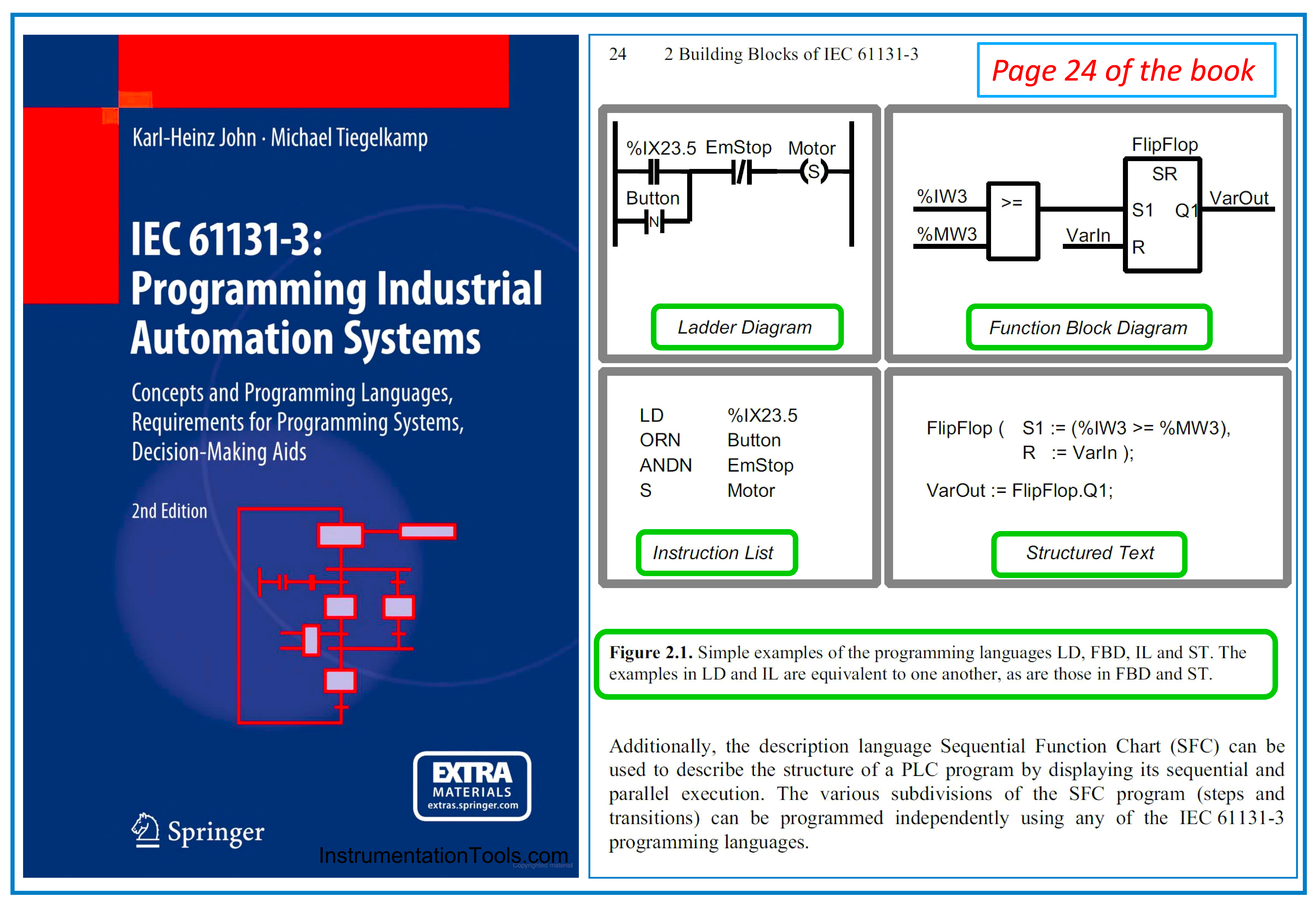
Figure-3: A very good book on IEC-61131-3 Standard
In Figure-3 the general structure format of four common languages further to the Sequential Function Chart (reflected on the book cover) is shown too. The details of such programming languages are out of the scope of this article, while the reader may refer to the mentioned book for any further information.
As mentioned before, following the IEC-61131-3 standard is a very good advantage that systems vendors highlight. For examples please see Figure-4.
Figure-4 shows the application of IEC-61131-3 in different (Programmable) Controllers, from small special items to highly complex process controllers.
Figure-5 shows an application of this standard in a big DCS for Process Plants. As this figure shows having the facility of following 5 standard languages makes the 5 good engineering tools for implementing aspects of such a system. Also comparing this Figure with Figure-1 shows us that applying different engineering facilities of DCS system will have reflections on different systems process functionalities (aspects).
Similarly, Figures 6 and 7 show applying IEC-61131-3 standard for making Engineering Tools for configuring Process Control System Aspects in another DCS System. Focusing more on Figure-6 we can find some advantages of applying the IEC-61131-3 standard in more detail, i.e.:
- International Standard Engineering Environment
- Compliant with IEC 61131-3 programming languages, allowing for vendor- and model-independent engineering.
- Five programming languages can be used selectively according to the purposes of use and applications, from sequence control to analog control.
The above advantages are commonly applicable to all today’s DCS Process Control Systems and inform us that such systems may use simultaneous Programming Languages for different Process Control System aspects (Functionalities).
Notice that in each Process Plant Project, we may need different Control Functions (Referring to Figure-1: Analog Controllers, Interlock Logic Control, Sequence Control,…) that using simultaneous different standard programming languages enables us to easily satisfy such targets. Figure-8 shows another example of applying such a facility from other vendors.
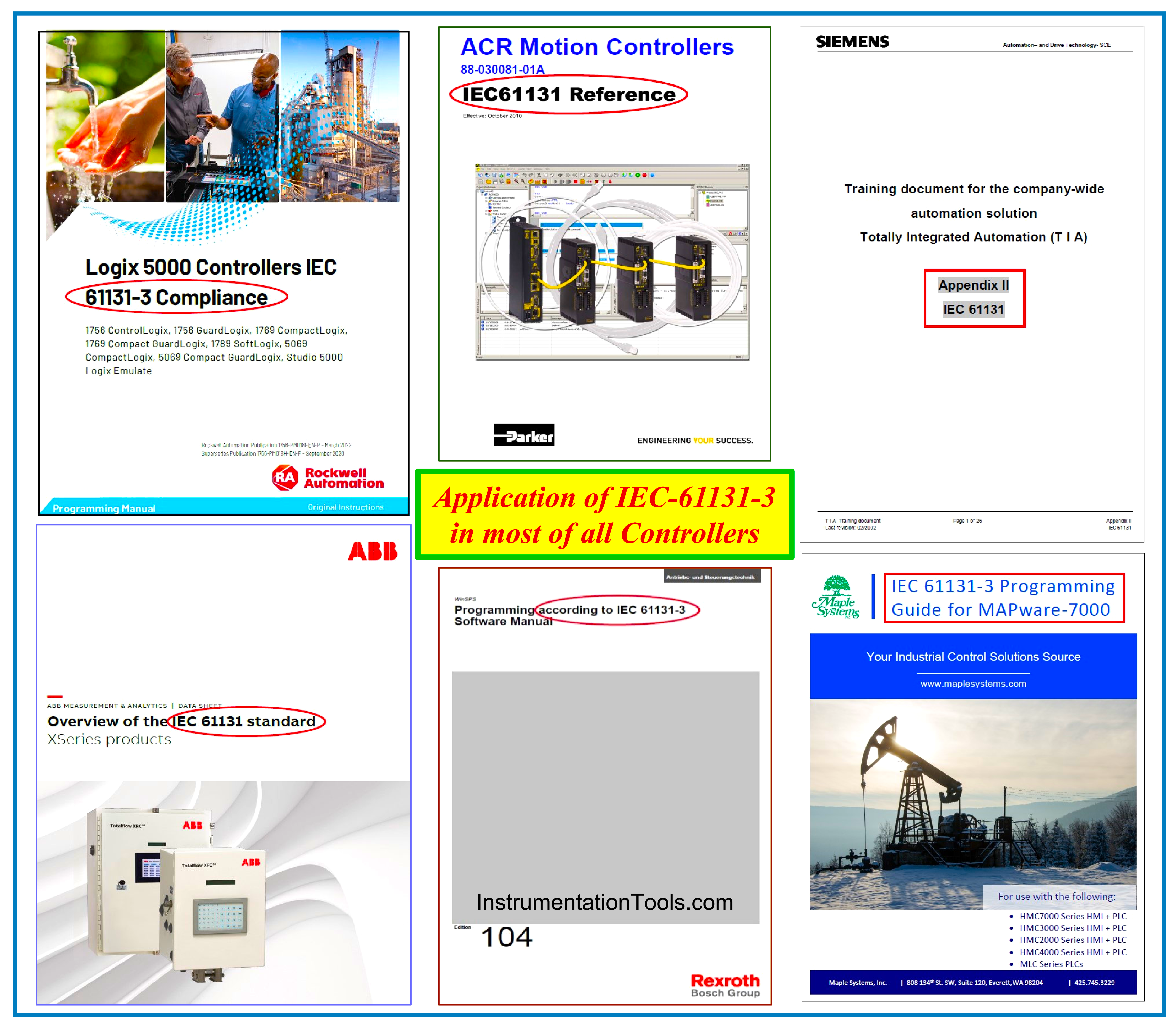
Figure-4: Application of IEC-61131-3 in most of all (Programmable) Controllers.
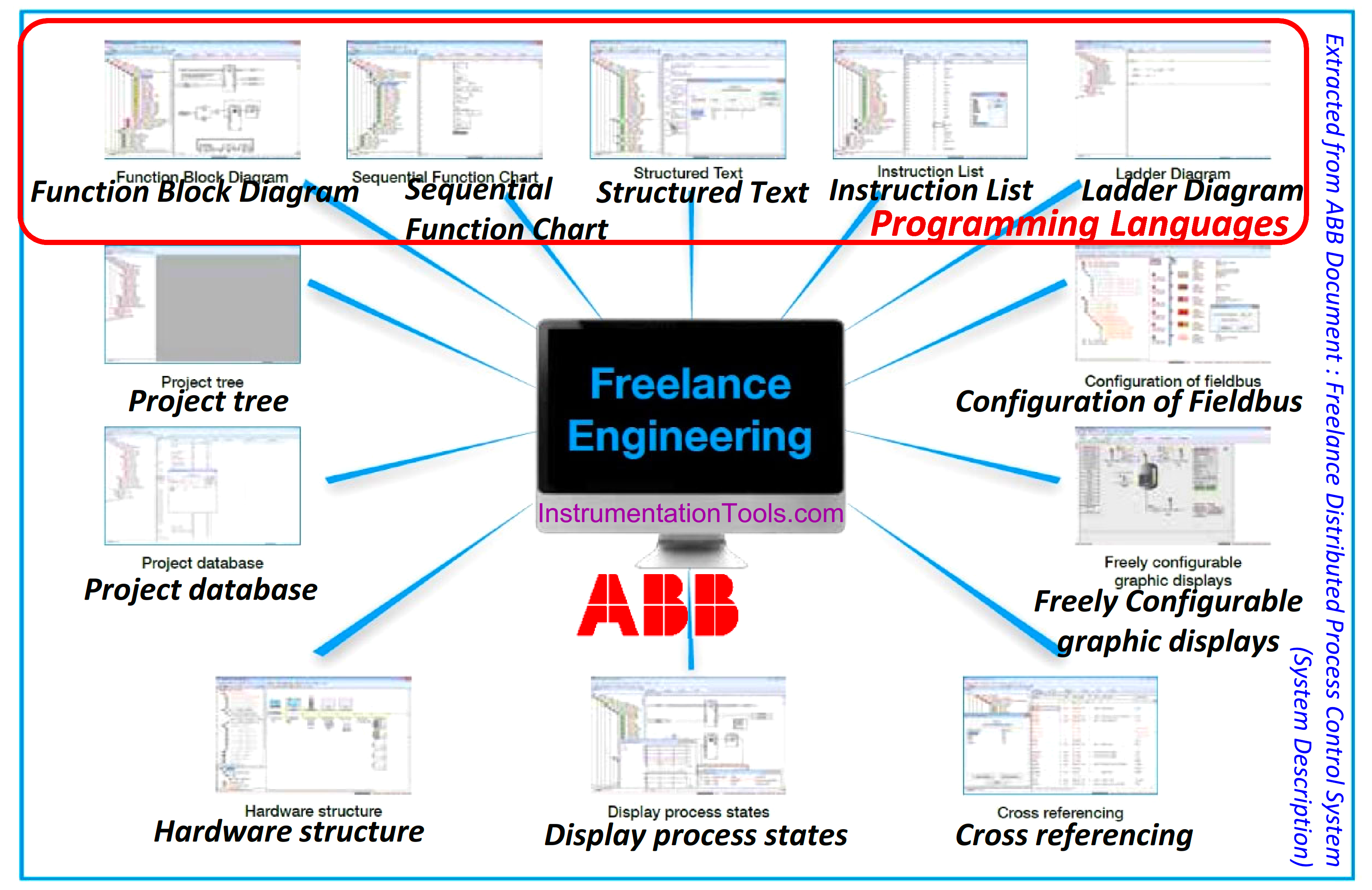
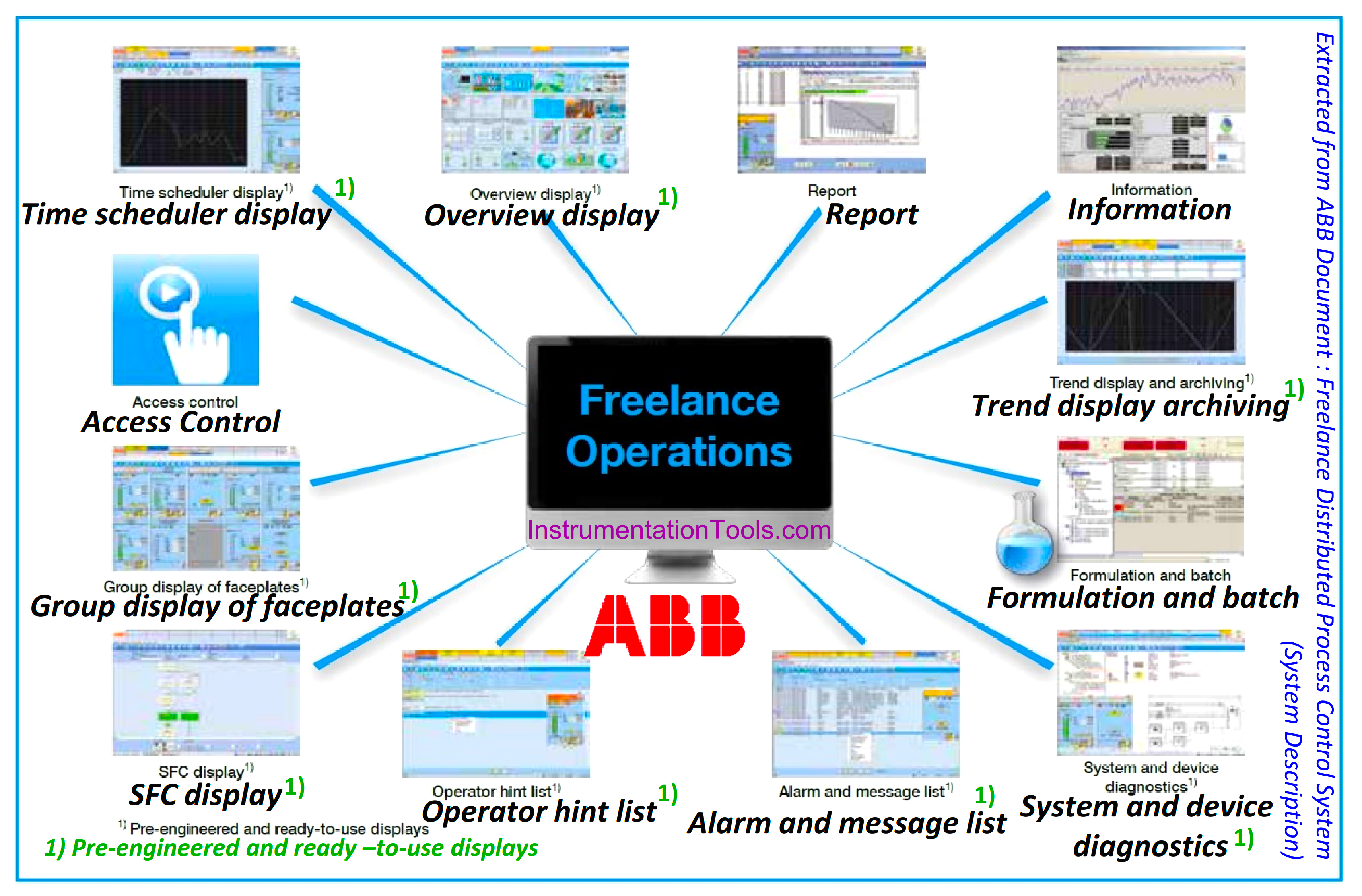
Figure-5: Applying ABB DCS Engineering Tools (including 5 IEC-61131-3 Programming Languages) for implementing Process Control System Aspects (Functionalities).
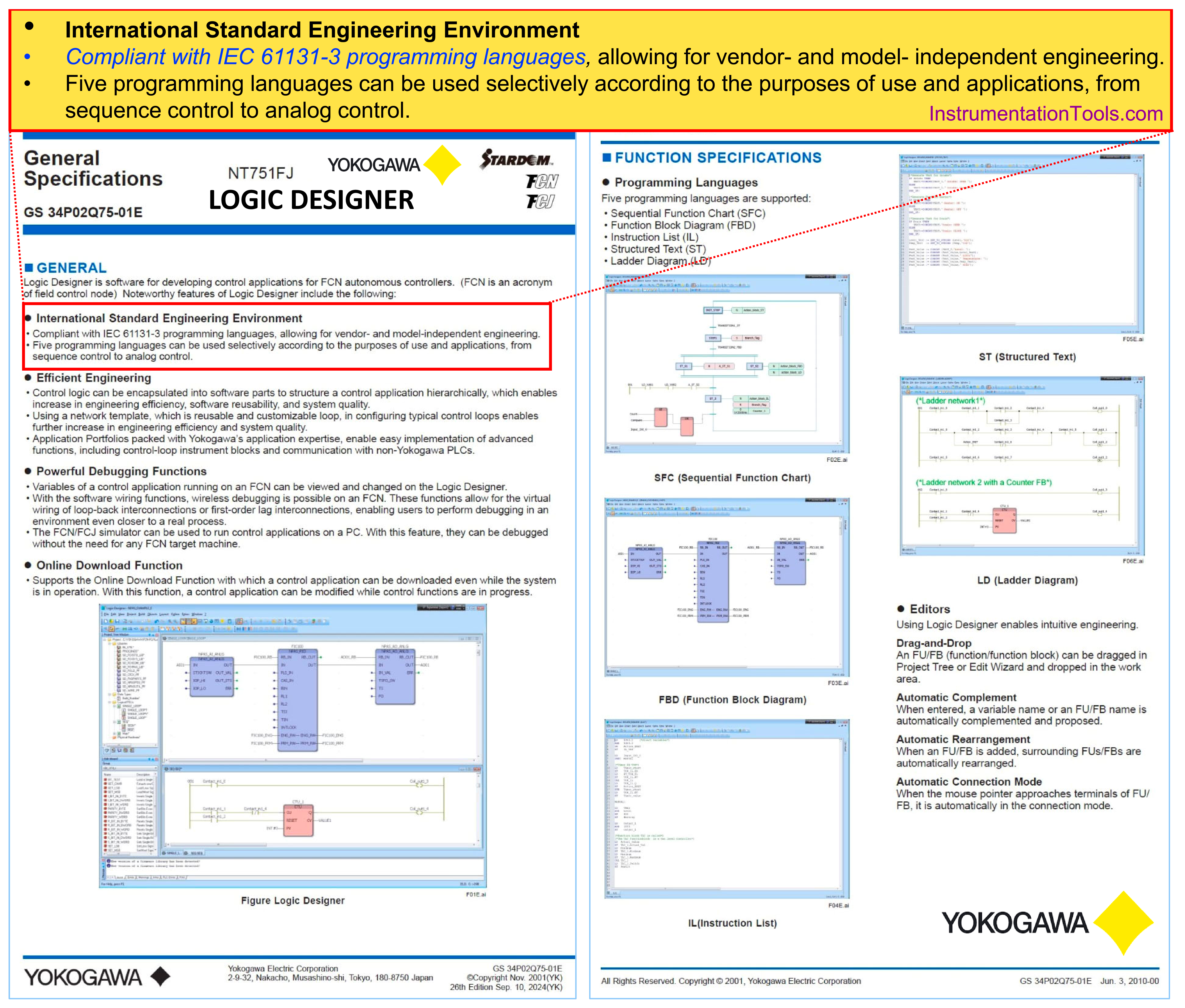
Figure-6: Advantages of IEC-61131-3 in Yokogawa Logic Designer Facility.
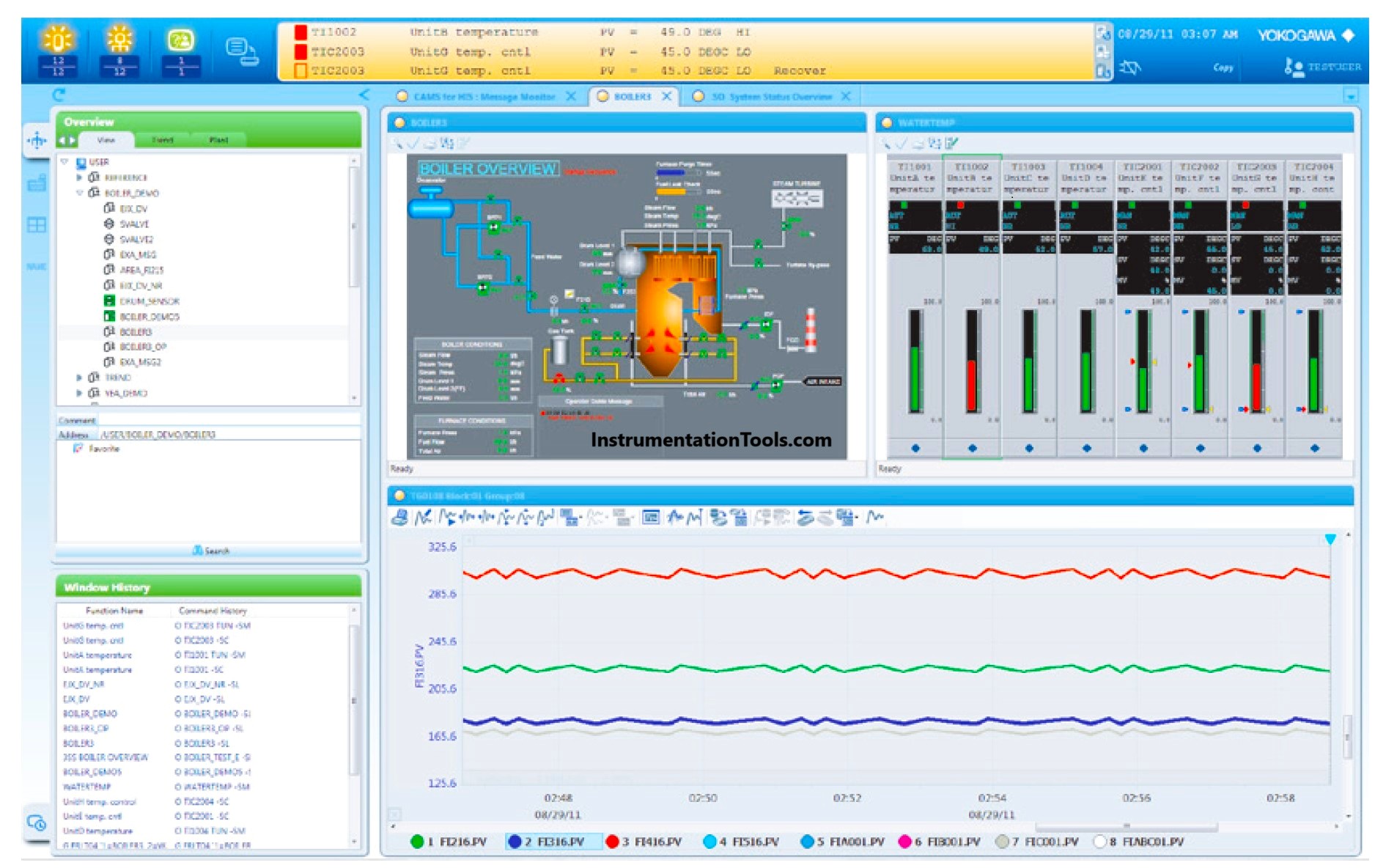
Figure-7: Applying Yokogawa Engineering Tools for Process Control System Aspects (Functionalities).
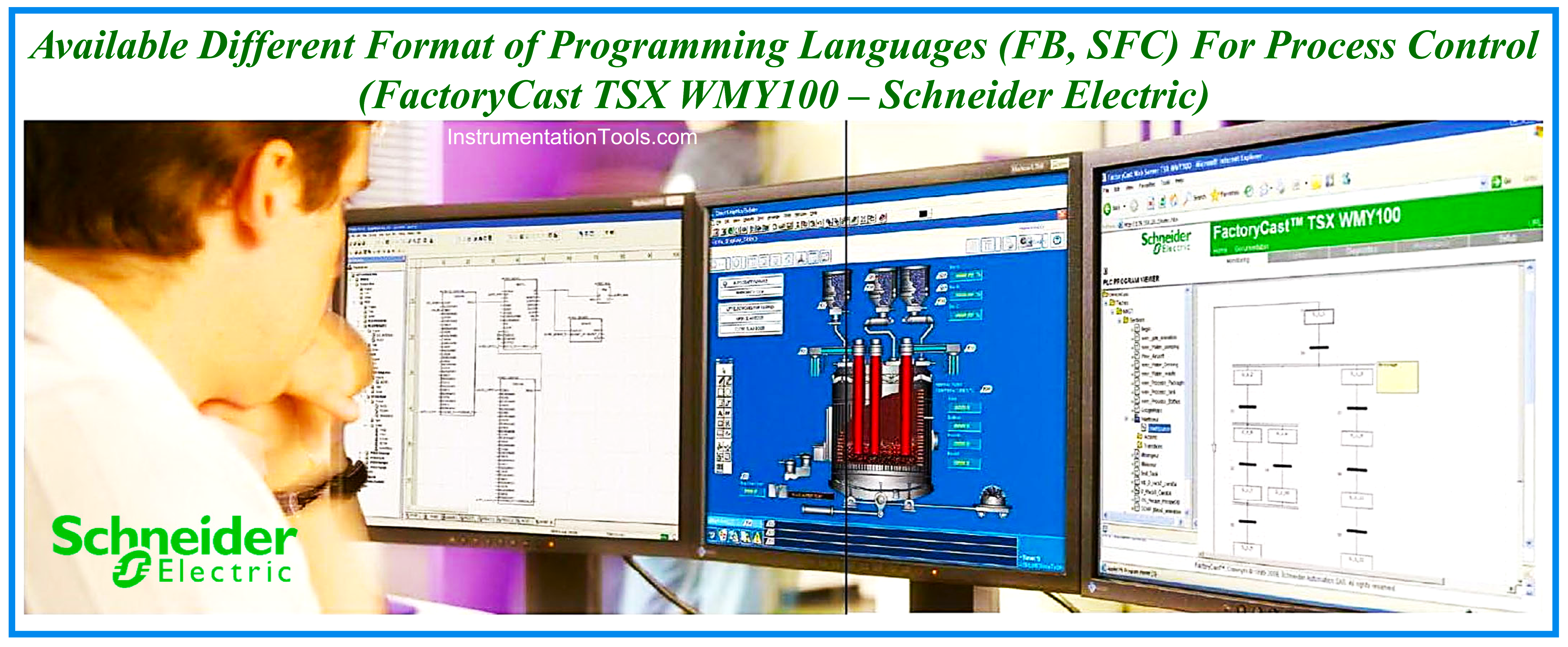
Figure-8: Applying Two Different Format of Programming Languages for Process Control Using Schneider Electric Programmable Controller System.
Implementing Design Logic Diagram in Process Control System
Implementing the provided Design Logic Diagram during Detail Design Engineering Phase of the Industrial Process Plant Project (just by some companies) is one of the responsibilities of the system vendor (otherwise vendor shall implement it based on all other received documents and data). However such Interlock Logics usually includes some functional actions which are definable by symbols of ISA 5.2 Standard.
As an example, the logics of SIS/ESD Systems (for Process Protection Functions) are classified in this way. Usually, Systems Vendors implement such Logic requirements by using Ladder Diagram (LD) or Function Block Diagram (FBD) languages. Figure-9 shows a sample of the SIS/ESD Logic Diagram which is implemented by the vendor programming language in the FBD format.
The similarity of Design Standard Logic Diagram symbols and diagram formats (provided based on ISA 5.2 standard) with those implemented in System Logic Diagram (based on IEC-61131-3 standard) will make some advantages. The main advantage will be an easily understandable system implemented logic diagram by many specialists (including Process Engineers and Site Operators). So any fault finding or process problems troubleshooting will be easier.
Figure-10 shows a realistic example of such similarity in the system implemented Interlock Logics with the provided Design Logic Diagram which made it easier to test the compliance of functionalities during acceptance tests (FAT/ SAT). As the figure shows, the system can specify the status of each signal by color changing, and hence the responsible specialists can find the validity of system-implemented functionalities. Of course, during the Plant Operation Phase, such color changes can help site specialists find the source of trouble or study the process conditions.
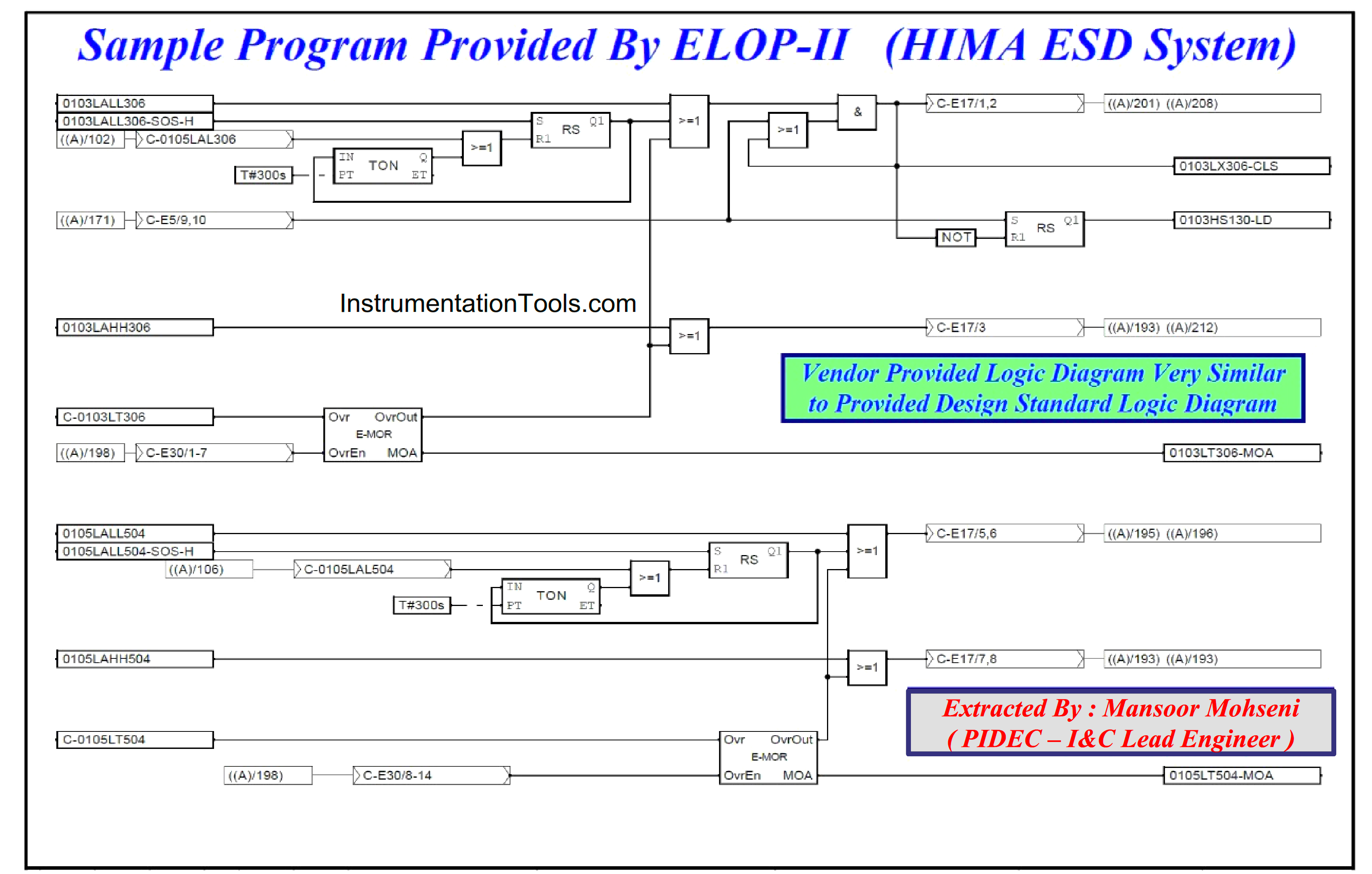
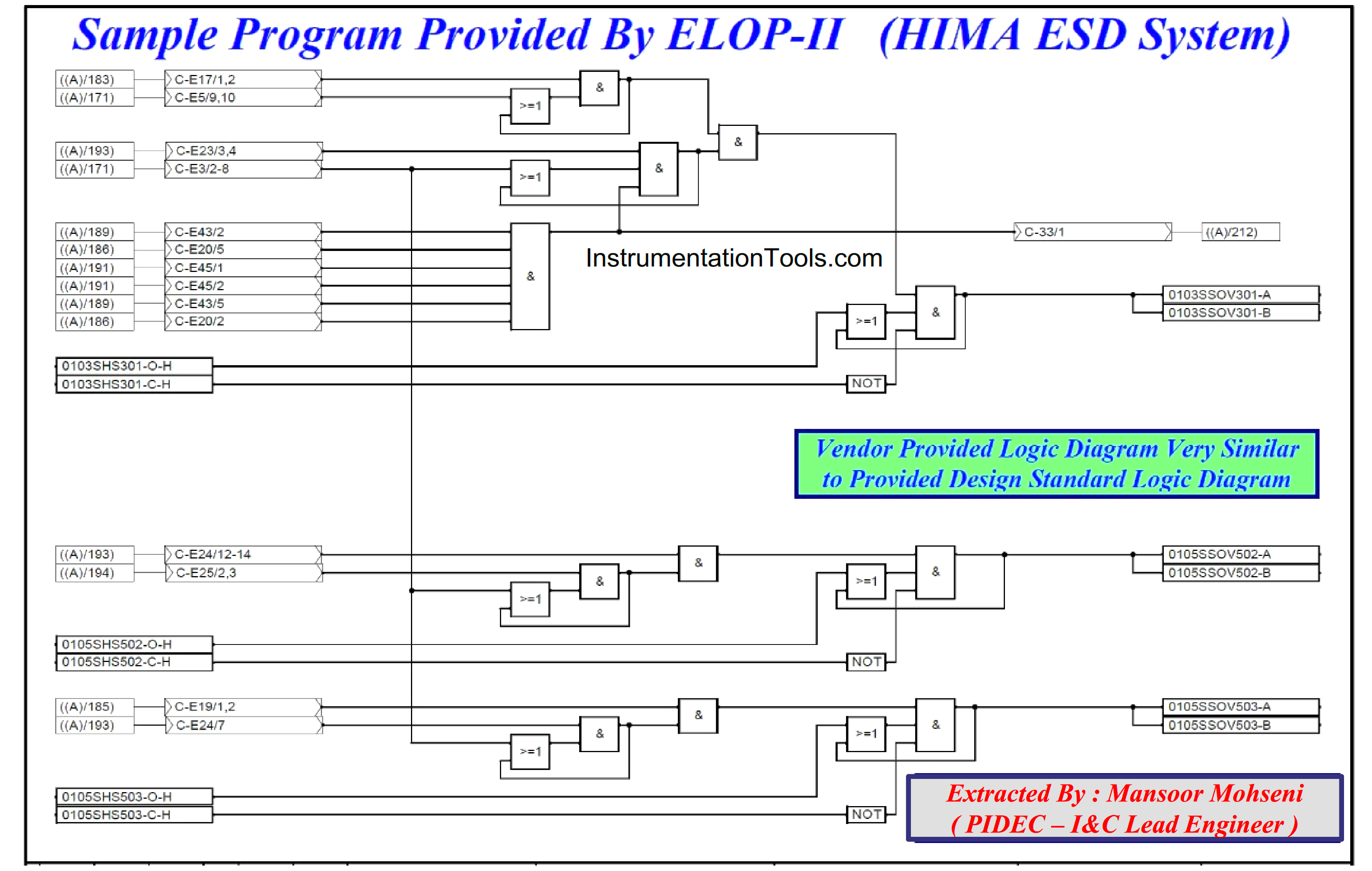
Figure-9: Sample of SIS/ESD Interlock Logic Diagram Implemented By HIMA ESD System –ELOP II (Programming Language).
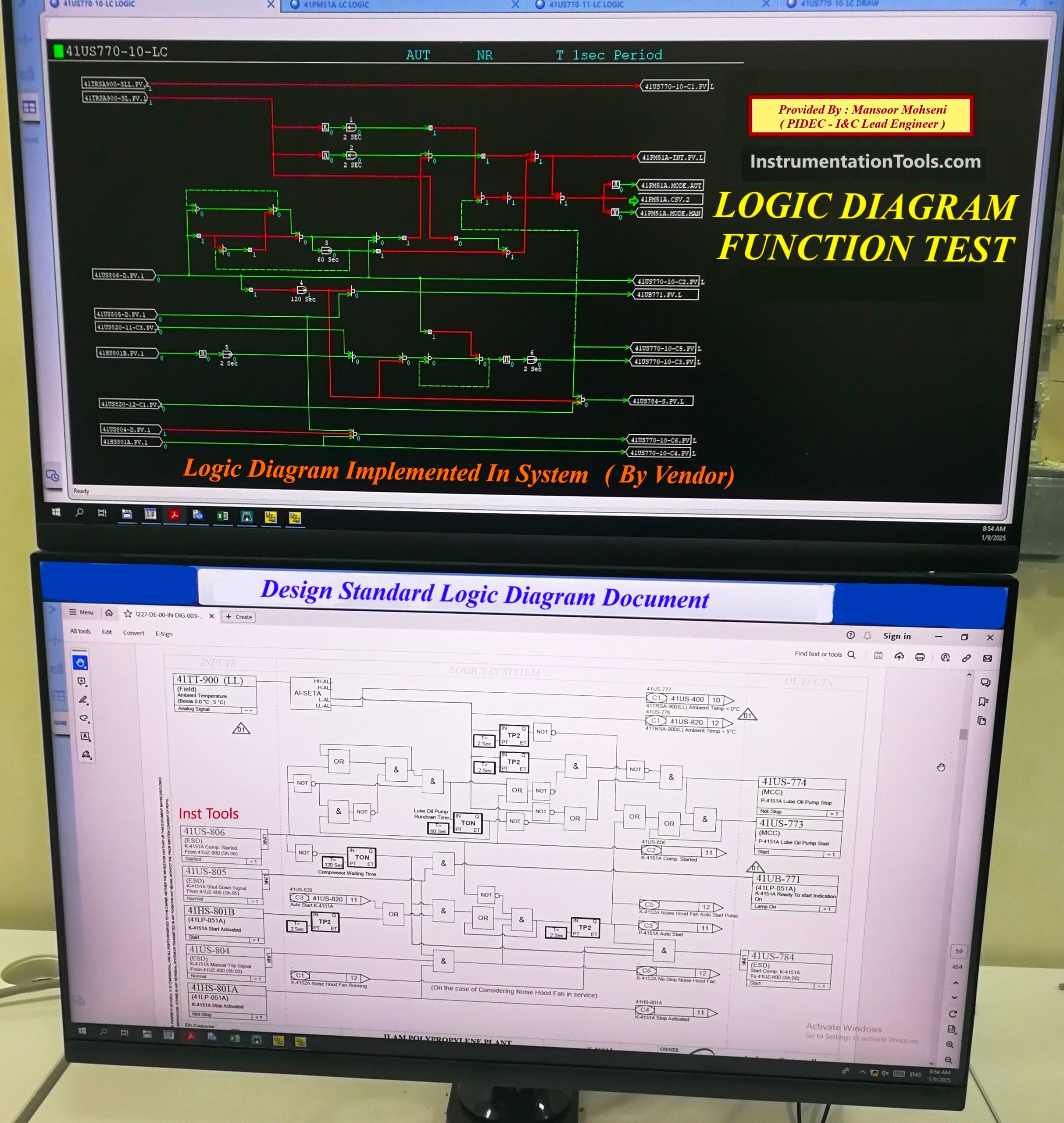
Figure-10: A realistic example of using the advantage of Similarity between System Implemented Logic with Design Standard Logic Diagram (During FAT/SAT).
Implementing All Required Process Functionalities By Control Systems Facilities
Referring to Figure-1 again we can remind that the Process Plant Requirements will need different functionalities further to Interlock Logic Control too. Such functionalities can be configured or programmed by System Facilities, most of which are provided based on IEC-61131-3 Programming Languages. Some of such functionalities may use dedicated language (tool) for implementation. For example, a Sequence Function Chart (SFC Language) may be a better tool for implementing Sequence Controls.
Generally, it shall be noticed that each Process Control System is a complex combination of different facilities interacting with each other and transferring data via some communication links. By such complex configurations, Systems can provide different functionality aspects for end users. We saw earlier the interaction of HMI graphics with implemented Logic Diagram and making good senses by color changing.
Close and exact coordination between Detail Design I&C Team and Systems Vendors specialists for using different systems facilities may produce very effective results for Process Operators. Figure-11 shows one of realistic example of such coordination for providing an Overall Process Logic Diagram (including Packages systems functionalities) that make a very good sense on Plant Overview conditions.
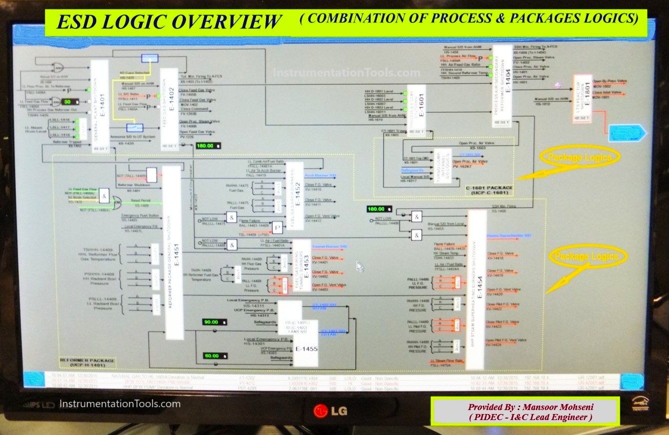
Figure-11: ESD Logic Overview Graphic Display as a result of good coordination for using different systems facilities.
In the end, it shall be mentioned that implementing Process Requirements in the different systems functionality aspects, needs practiced skillful specialists in different teams (including Systems Vendors and Detail Design I&C) for caring a lot of items and complexities. Some of them may be explicit, but some of them are hidden and may have great effects. CPU Loads and execution cycle times are two examples of such hidden items that are very important and have great effects, especially in big Process Plant projects.
References:
- Process Control & Safety Systems Logics Implementation Cycle
- Design Logic Diagram with Standard Formats for Process Control
- Design View of Supplying Industrial Process Control Systems
- Vendor View of Supplying Process Control & Safety System