This article discusses an Automatic Parking System equipped with a vehicle counting function using Siemens TIA-Portal. The system is designed to efficiently manage parking areas with two operational modes: automatic and manual. In manual mode, the operator can Open or Close the parking gate using the control buttons. The system can detect vehicles entering and exiting, record the number of vehicles in real-time, and ensure that the parking capacity is not exceeded. Additionally, the system is equipped with indicators to display the parking condition, whether it is full or when empty slots are available.
Program Objective
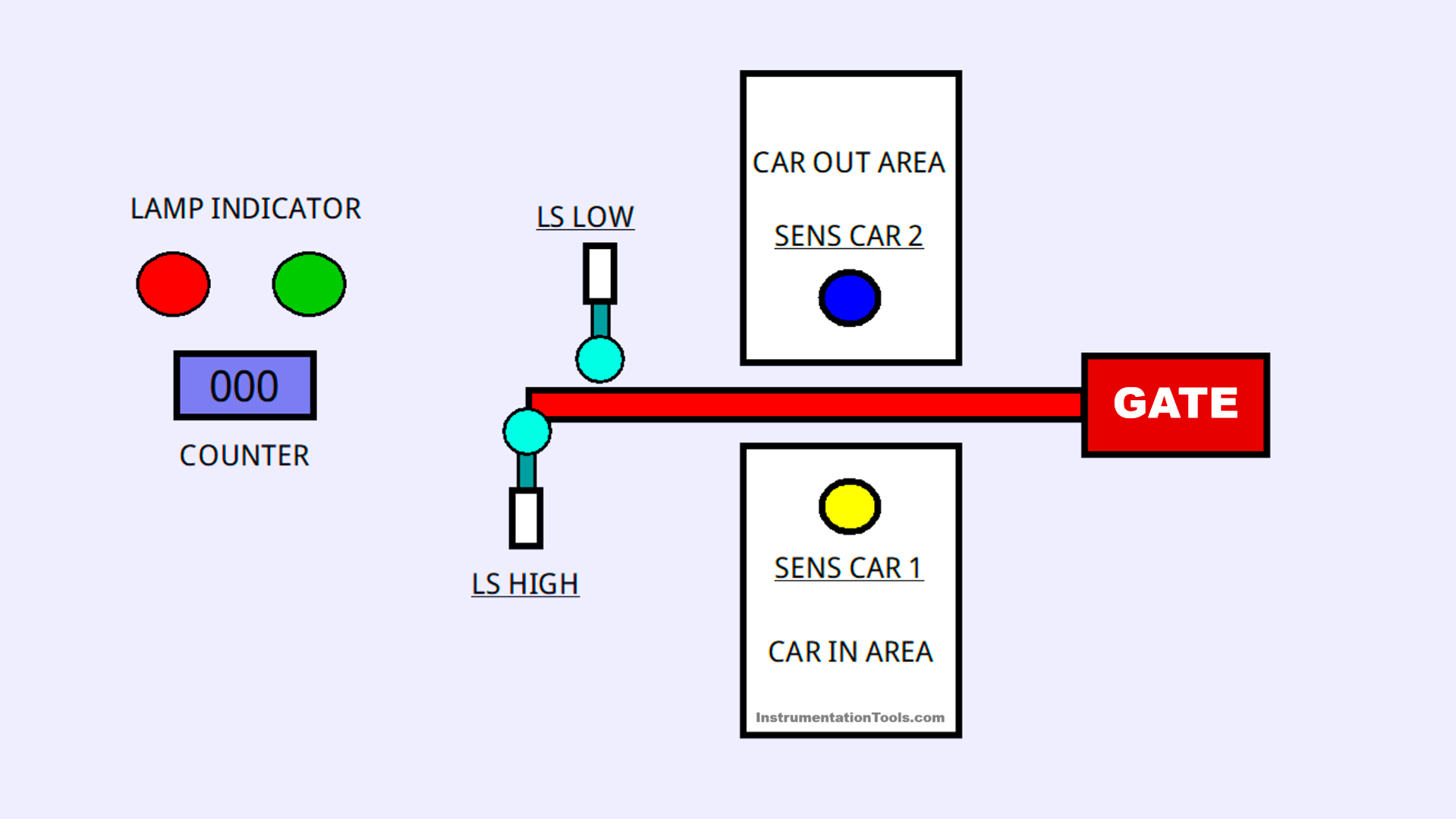
Parking System Steps:
- System Initialization:
- The system is configured with an initial parking capacity of 30 slots.
- The system is in Standby mode and ready to operate.
- Vehicle Entry Process:
- A vehicle approaches the Entry Gate, and the automatic sensor detects its presence.
- If parking slots are available, the Green indicator Lamp will turn On, the gate will Open automatically, the vehicle is allowed to enter, and the system will add (+1) to the vehicle Counter.
- If the parking area is full, the Red indicator Lamp will turn On, and the gate will remain closed.
- Vehicle Exit Process:
- A vehicle approaches the Exit Gate, and the automatic sensor detects its presence.
- The gate will open automatically, the vehicle exits, and the system will subtract (-1) from the vehicle Counter.
- Parking Capacity Management:
- The system ensures that the number of vehicles inside the parking area does not exceed the maximum capacity.
- If the parking area is full, the Entry Gate will not Open until a vehicle exits.
- Manual Mode:
- The system can be operated manually using the UP/Down buttons to Open or Close the gate.
- Alarm and Indicators:
- The Green indicator Lamp will turn On if parking slots are available.
- The Red indicator Lamp will turn On if the parking area is full.
Program Inputs and Outputs
| S.No. | Comment | Input (I) | Output(Q) | Memory Bit | Memory Word |
| 1 | PB_START | I0.0 | |||
| 2 | PB_STOP | I0.1 | |||
| 3 | AUTO/MANUAL | I0.2 | |||
| 4 | PB_UP | I0.3 | |||
| 5 | LS_HIGH | I0.4 | |||
| 6 | PB_DOWN | I0.5 | |||
| 7 | LS_LOW | I0.6 | |||
| 8 | SENS_CAR_1 | I0.7 | |||
| 9 | SENS_CAR_2 | I1.0 | |||
| 10 | RESET_COUNTER | I1.1 | |||
| 11 | GATE_UP | Q0.0 | |||
| 12 | GATE_DOWN | Q0.1 | |||
| 13 | LAMP_GREEN | Q0.2 | |||
| 14 | LAMP_RED | Q0.3 | |||
| 15 | CAR_COUNT | MW0 | |||
| 16 | SYSTEM_ON | M2.0 | |||
| 17 | GATE_UP_MANUAL | M2.1 | |||
| 18 | GATE_DOWN_MANUAL | M2.2 | |||
| 19 | GATE_UP_AUTO_IN | M2.3 | |||
| 20 | GATE_DOWN_AUTO_IN | M2.4 | |||
| 21 | GATE_UP_AUTO_OUT | M2.5 | |||
| 22 | GATE_DOWN_AUTO_OUT | M2.6 | |||
| 23 | INTERLOCK_CAR_IN | M2.7 | |||
| 24 | INTERLOCK_CAR_OUT | M3.0 | |||
| 25 | IR1_SENS_CAR_1 | M3.1 | |||
| 26 | IR2_SENS_CAR_1 | M3.2 | |||
| 27 | IR1_SENS_CAR_2 | M3.3 | |||
| 28 | IR2_SENS_CAR_2 | M3.4 |
Automatic Parking with Vehicle Counter
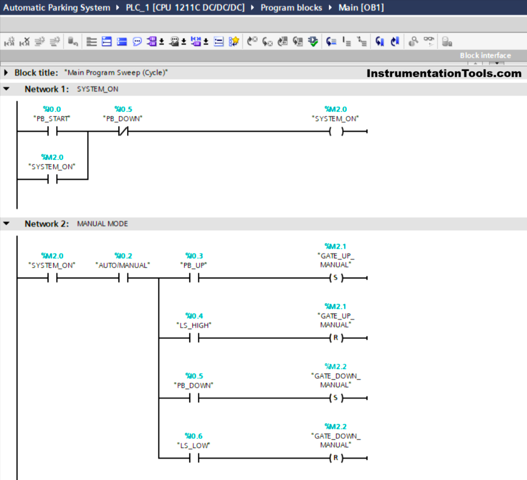
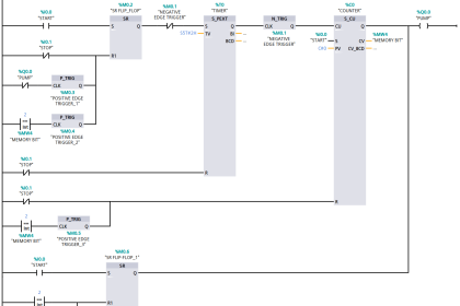
NETWORK 1 (SYSTEM_ON)
In this network, when the PB_START (I0.0) button is Pressed, the memory bit SYSTEM_ON (M2.0) will be in the HIGH state. The memory bit SYSTEM_ON (M2.0) will remain in the HIGH state even though the PB_START (I0.0) button has been Released. Because it uses Latching.
If the PB_STOP (I0.1) button is Pressed, the memory bit SYSTEM_ON (M2.0) will be in the LOW state.
NETWORK 2 (MANUAL MODE)
In this Network, when the NO contact of the memory bit SYSTEM_ON (M2.0) and the AUTO/MANUAL (I0.2) selector switch are in the HIGH state, and the PB_UP (I0.3) button has been Pressed, the memory bit GATE_UP_MANUAL (M2.1) will be in the HIGH state.
When the limit switch LS_HIGH (I0.4) is in the HIGH state, the memory bit GATE_UP_MANUAL (M2.1) will be in the LOW state.
When the NO contact of the memory bit SYSTEM_ON (M2.0) and AUTO/MANUAL (I0.2) selector switch is in the HIGH state and the PB_DOWN (I0.5) button has been Pressed, the memory bit GATE_DOWN_MANUAL (M2.2) will be in the HIGH state.
When the limit switch LS_LOW (I0.6) is in the HIGH state, the memory bit GATE_DOWN_MANUAL (M2.2) will be in the LOW state.
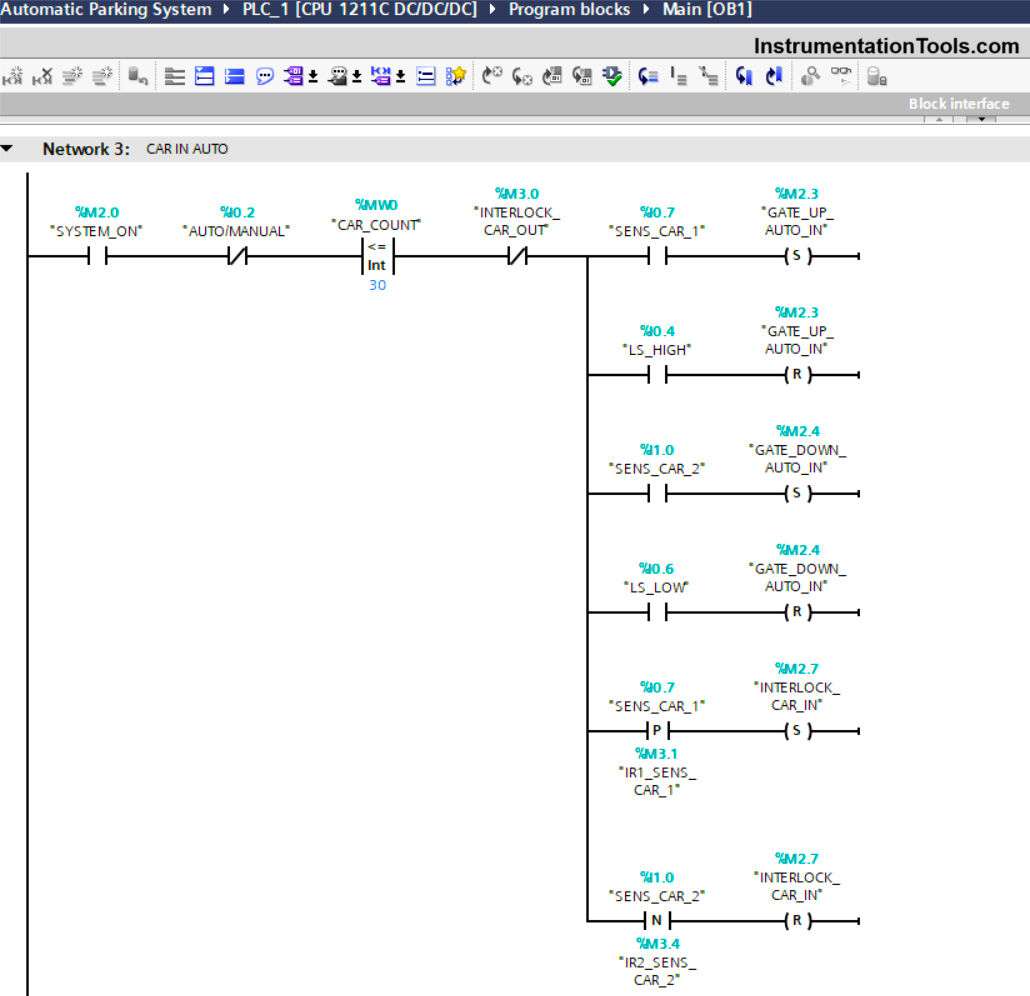
NETWORK 3 (CAR IN AUTO)
In this network, when the NO contact of the memory bit SYSTEM_ON (M2.0) and the SENS_CAR_1 (I0.7) sensor in the HIGH state and the value of the memory word CAR_COUNT (MW0) is Less Than Or Equal To “30”, then the memory bit GATE_UP_AUTO_IN (M2.3) and INTERLOCK_CAR_IN(M2.7) will be in the HIGH state.
If the NO contact of the limit switch LS_HIGH (I0.4) is in the HIGH state, then the memory bit GATE_UP_AUTO_IN (M2.3) will be in the LOW state.
When the NO contact of the memory bit SYSTEM_ON (M2.0) and the sensor SENS_CAR_2 (I1.0) are in the HIGH state and the value of the memory word CAR_COUNT (MW0) is Less Than Or Equal To “30”, then the memory bit GATE_DOWN_AUTO_IN (M2.4) will be in the HIGH state.
If the NO contact of the limit switch LS_LOW (I0.6) is in the HIGH state, then the memory bit GATE_DOWN_AUTO_IN (M2.4) will be in the LOW state.
When the NO contact of the SENS_CAR_2 (I1.0) sensor changes to the LOW state, the memory bit INTERLOCK_CAR_IN (M2.7) will become LOW state.
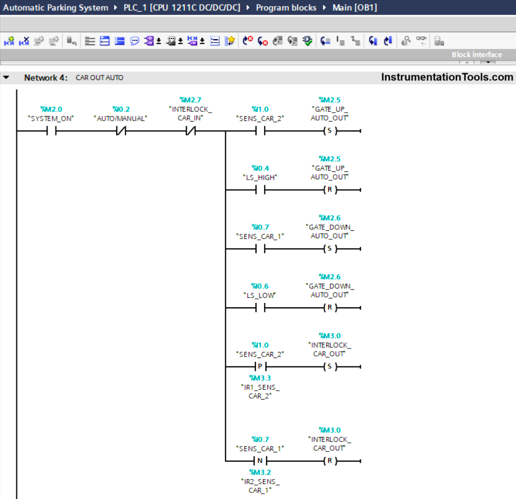
NETWORK 4 (CAR OUT AUTO)
In this network, when the NO contact of the memory bit SYSTEM_ON (M2.0) and the SENS_CAR_2 (I1.0) sensor are in the HIGH state, then the memory bit GATE_UP_AUTO_OUT (M2.5) and INTERLOCK_CAR_OUT (M3.0) will be in the HIGH state. state.
If the NO contact of the limit switch LS_HIGH (I0.4) is in the HIGH state, then the memory bit GATE_UP_AUTO_OUT (M2.5) will be in the LOW state.
When the NO contact of the memory bit SYSTEM_ON (M2.0) and the SENS_CAR_1 (I0.7) sensor are in the HIGH state, the memory bit GATE_DOWN_AUTO_OUT (M2.6) will be in the HIGH state.
If the NO contact of the limit switch LS_LOW (I0.6) is in the HIGH state, then the memory bit GATE_DOWN_AUTO_OUT (M2.6) will be in the LOW state.
When the NO contact of the SENS_CAR_1 (I0.7) sensor changes to the LOW state, the memory bit INTERLOCK_CAR_OUT (M3.0) will become LOW state.
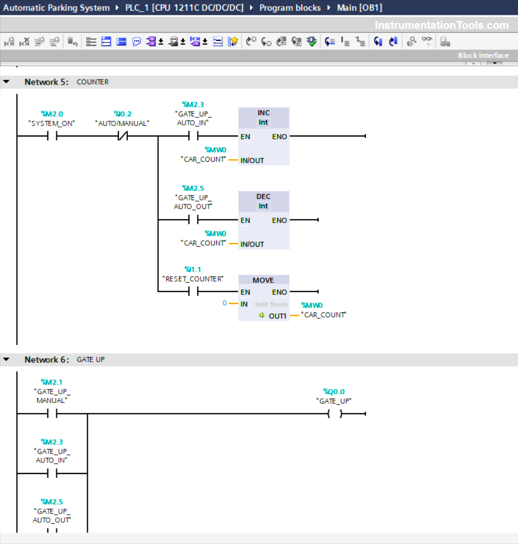
NETWORK 5 (COUNTER)
In this network, the value in the memory word CAR_COUNT (MW0) will increase (+1) if the NO contact of the memory bits SYSTEM_ON (M2.0) and GATE_UP_AUTO_IN (M2.3) are in the HIGH state.
And the value in the memory word CAR_COUNT (MW0) will decrease (-1) if the NO contact of the memory bit SYSTEM_ON (M2.0) and GATE_UP_AUTO_OUT (M2.5) is in the HIGH state.
The value in the memory word CAR_COUNT (MW0) will be reset to the zero value “0” when the NO contact of the memory bit SYSTEM_ON (M2.0) in the HIGH state and the RESET_COUNTER (I1.1) button is Pressed.
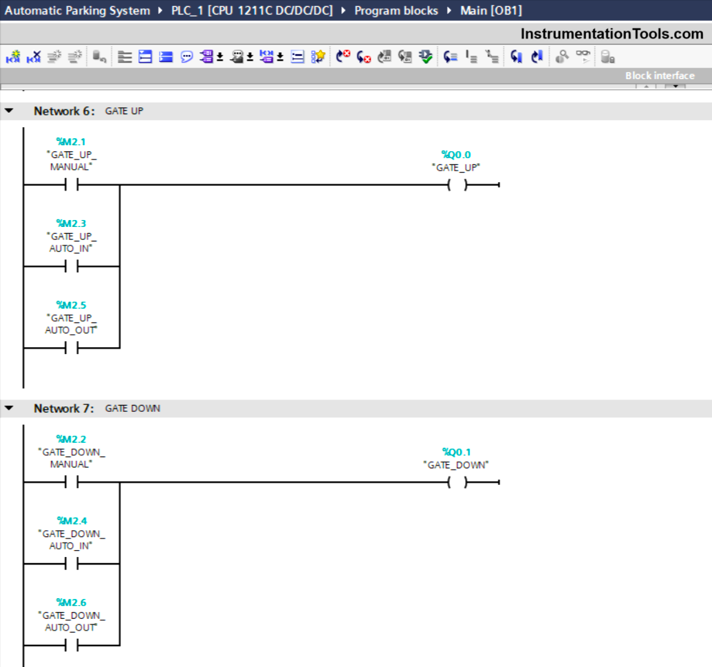
NETWORK 6 (GATE UP)
In this Network, the GATE_UP (Q0.0) output will be ON when the NO contact of the memory bits GATE_UP_MANUAL (M2.1) or GATE_UP_AUTO_IN (M2.3), or GATE_UP_AUTO_OUT (M2.5) is in the HIGH state.
NETWORK 7 (GATE DOWN)
In this Network, the GATE_DOWN (Q0.1) output will be ON when the NO contact of the memory bits GATE_DOWN_MANUAL (M2.2) or GATE_DOWN_AUTO_IN (M2.4), or GATE_DOWN_AUTO_OUT (M2.6) is in the HIGH state.
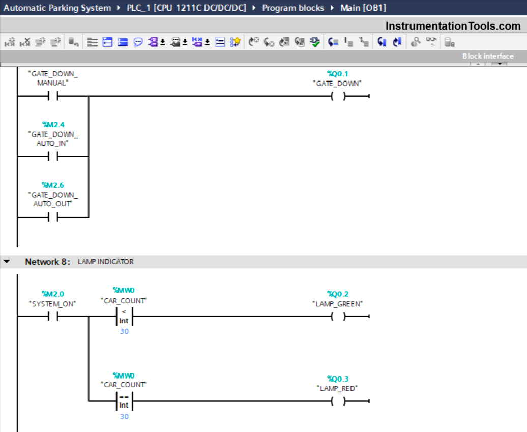
NETWORK 8 (LAMP INDICATOR)
In this network, when the NO contact of the memory bit SYSTEM_ON (M2.0) and the value of the memory word CAR_COUNT (MW0) is Less Than “30”, then the output LAMP_GREEN (Q0.2) will be ON.
When the NO contact of the memory bit SYSTEM_ON (M2.0) and the value of the memory word CAR_COUNT (MW0) is Equal To “30”, then the output LAMP_RED (Q0.3) will be ON.
Read Next:
- Schneider PLC Manual Sequential Machine
- PLC Bottle’s Capping with Rotating Mechanism
- Parking Garage Indicator Automation System
- PLC Interlock Logic with First Input Priority
- Complex Car Parking Logic in LS Electric PLC