Learn the RTC function (Real Time Clock) on the Automatic Highway Lights program using the Omron PLC CX-Programmer software for beginners.
Automatic Highway Lights
This PLC program has 5 buttons and 1 Selector Switch, The START_SYSTEM (0.00) button is used to turn ON the system, the STOP_SYSTEM (0.01) button is used to turn OFF the system, and the LAMP1_BUTTON (0.03) button is used to turn ON Lamp 1, the LAMP2_BUTTON (0.04) button is used to turn ON Lamp 2, the LAMP3_BUTTON (0.05) button is used to turn ON Lamp 3.
Selector Switch SELECTOR_MODE (0.02) is used to select Manual or Auto system mode.
By default, the PLC system will Run in Manual mode. The system will be in a standby state when the START_SYSTEM (0.00) button is Pressed, and the system will be OFF when the STOP_SYSTEM (0.01) button is Pressed.
Manual Mode
When the system is Running in Manual mode all outputs can only be turned ON using the buttons. Output LAMP1 (100.00) will be ON if the LAMP1_BUTTON (0.03) button is Pressed, Output LAMP2 (100.02) will be ON if the LAMP2_BUTTON (0.04) button is Pressed, and Output LAMP3 (100.03) will be ON if the LAMP3_BUTTON (0.05) button is Pressed.
Auto Mode
In general, highway lights will turn On in the evening (17.00) and will automatically turn OFF in the morning (06.00). So the time parameters need to be set in the memory words SV_HOUR_ON (D0-D1) “D0 = 0000 & D1 = 0017” and SV_HOUR_OFF (D10-D11) “D10 = 0000 & D11 = 0006”.
Inputs and Outputs
| Comment | Input (I) | Output (Q) | Word Memory | Memory Bits |
| START_SYSTEM | 0.00 | |||
| STOP_SYSTEM | 0.01 | |||
| SELECTOR_MODE | 0.02 | |||
| LAMP1_BUTTON | 0.03 | |||
| LAMP2_BUTTON | 0.04 | |||
| LAMP3_BUTTON | 0.05 | |||
| LAMP1 | 100.00 | |||
| LAMP2 | 100.01 | |||
| LAMP3 | 100.02 | |||
| SV_HOUR_ON | D0-D1 | |||
| SV_HOUR_OFF | D10-11 | |||
| SYSTEM_ON | W0.00 | |||
| MANUAL_MODE | W0.01 | |||
| AUTO_MODE | W0.02 | |||
| IR_LAMP1 | W0.10 | |||
| IR_LAMP2 | W0.11 | |||
| IR_LAMP3 | W0.12 | |||
| IR_AUTO | W0.13 |
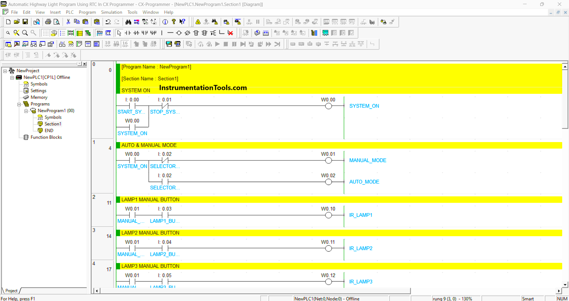
Program in Omron PLC
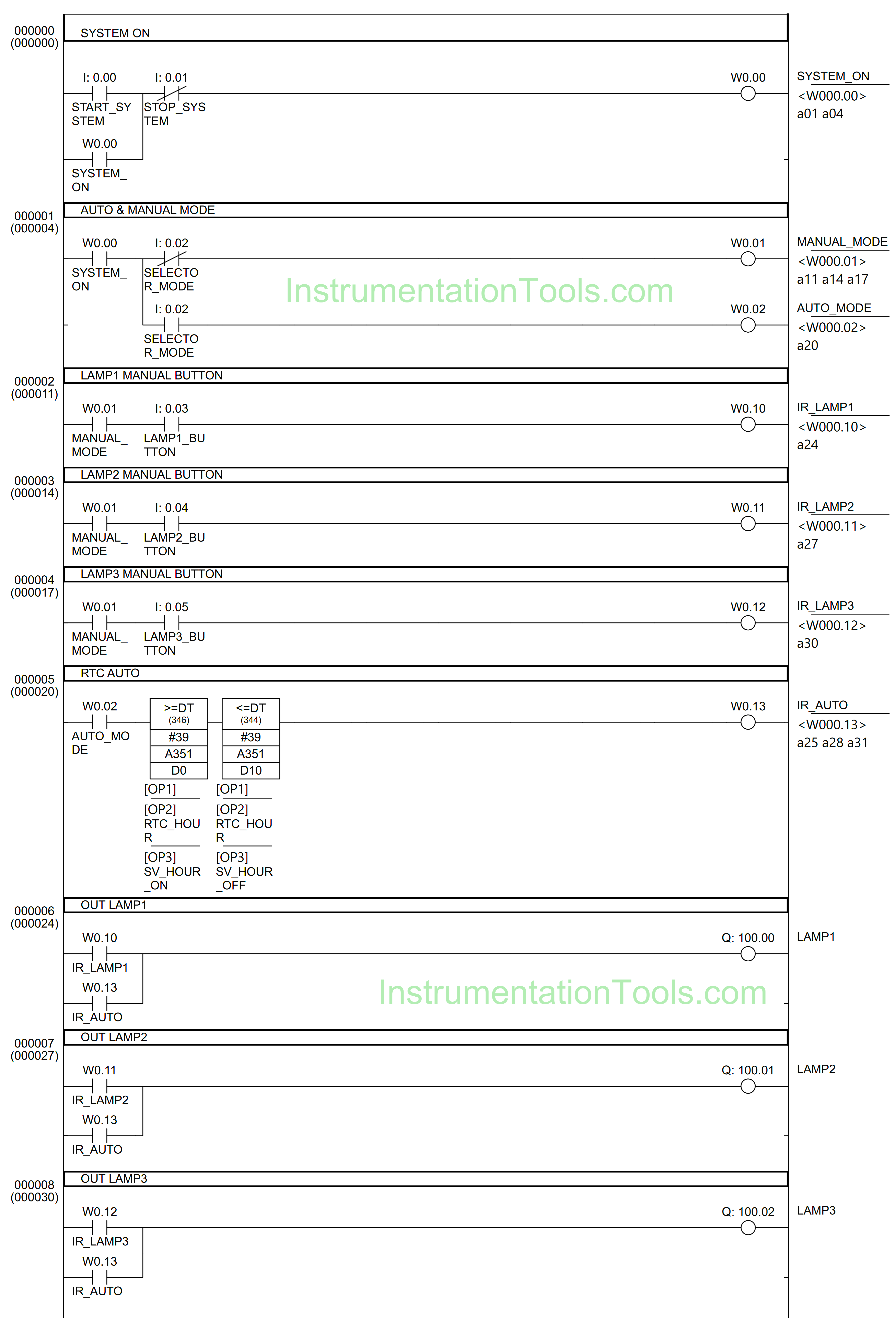
RUNG 0 (SYSTEM ON)
In this Rung, when the START_SYSTEM (0.00) button is pressed, the memory bit SYSTEM_ON (W0.00) changes to the HIGH state. The memory bit SYSTEM_ON (W0.00) will remain in the HIGH state even though the START_SYSTEM (0.00) button has been Released because it uses Latching.
If the STOP_SYSTEM (0.01) button is Pressed, the memory bit SYSTEM_ON (W0.00) will change to a LOW state.
RUNG 1 (AUTO & MANUAL MODE)
In this Rung, when the NO contact of memory bit SYSTEM_ON (W0.00) in the HIGH state and the Selector Switch SELECTOR_MODE (0.02) in the LOW state, the memory bit MANUAL_MODE (W0.01) will change to the HIGH state.
When the Selector Switch SELECTOR_MODE (0.02) is changed to HIGH state, the memory bit AUTO_MODE (W0.02) will become HIGH and the memory bit MANUAL_MODE (W0.01) will become LOW state.
RUNG 2 (LAMP 1 MANUAL BUTTON)
In this Rung, when the NO contact of memory bit SYSTEM_ON (W0.00) in the HIGH state and the LAMP1_BUTTON (0.03) button is pressed, the memory bit IR_LAMP1 (W0.10) will become a HIGH state.
RUNG 3 (LAMP 2 MANUAL BUTTON)
In this Rung, when the NO contact of memory bit SYSTEM_ON (W0.00) is in the HIGH state and the LAMP2_BUTTON (0.04) button is pressed, the memory bit IR_LAMP2 (W0.11) will become a HIGH state.
RUNG 4 (LAMP 3 MANUAL BUTTON)
In this Rung, when the NO contact of memory bit SYSTEM_ON (W0.00) is in the HIGH state and LAMP3_BUTTON (0.05) button is pressed, the memory bit IR_LAMP3 (W0.12) will become a HIGH state.
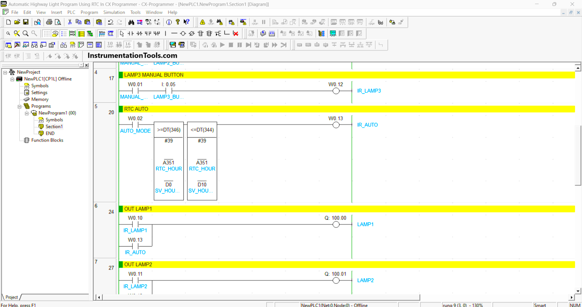
RUNG 5 (RTC AUTO)
In this Rung, when the NO contact of memory bit AUTO_MODE (W0.02) in the HIGH state and the RTC time is above “17.00”, then the memory bit IR_AUTO (W0.13) will change to the HIGH state.
The memory bit IR_AUTO (W0.13) will change to LOW state when the RTC time is above “06.00”.
RUNG 6 (OUT LAMP1)
The LAMP1 (100.00) output will be ON if the NO contact of memory bit IR_LAMP1 (W0.10) or IR_AUTO (W0.13) is in the HIGH state.
RUNG 7 (OUT LAMP2)
The LAMP2 (100.02) output will be ON if the NO contact of memory bit IR_LAMP2 (W0.11) or IR_AUTO (W0.13) is in the HIGH state.
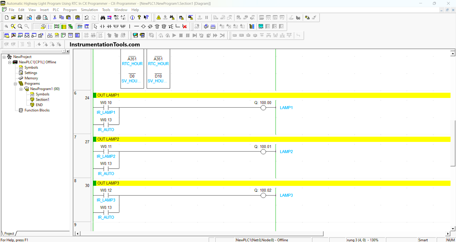
RUNG 8 (OUT LAMP3)
The LAMP3 (100.03) output will be ON if the NO contact of memory bit IR_LAMP3 (W0.12) or IR_AUTO (W0.13) is in the HIGH state.
Read Next:
- PLC Product Sticker Machine with Weighing
- Automatic Exhaust Fan XG5000 PLC Program
- Perfume Mixing and Filling System PLC Logic
- Waste-Burning System OMRON PLC Logic
- Water Pump PLC Program CX-Programmer