Design a simple automatic curtain control system using a PLC programming solution for practicing the ladder logic with example problems.
Note: Please consider that this PLC program is for education purposes to learn ladder logic.
Automatic Curtain Control
Problem Statement:
Design a PLC ladder logic for the following application.
We are using one Button to control the curtain.
When the Start Button is pressed, the Curtain should Open and remain open for 30 seconds before closing automatically.
If the Start Button is pressed again, the Curtains will remain Open for 30 seconds more.
Industrial Automation Videos
Learn about the industrial automation with our tutorials and videos.
This video covers the PLC curtain program explanation.
I/O
Digital Inputs:
Start Button: I0.0
Digital Outputs:
Curtain: Q0.0
PLC Programming Solution
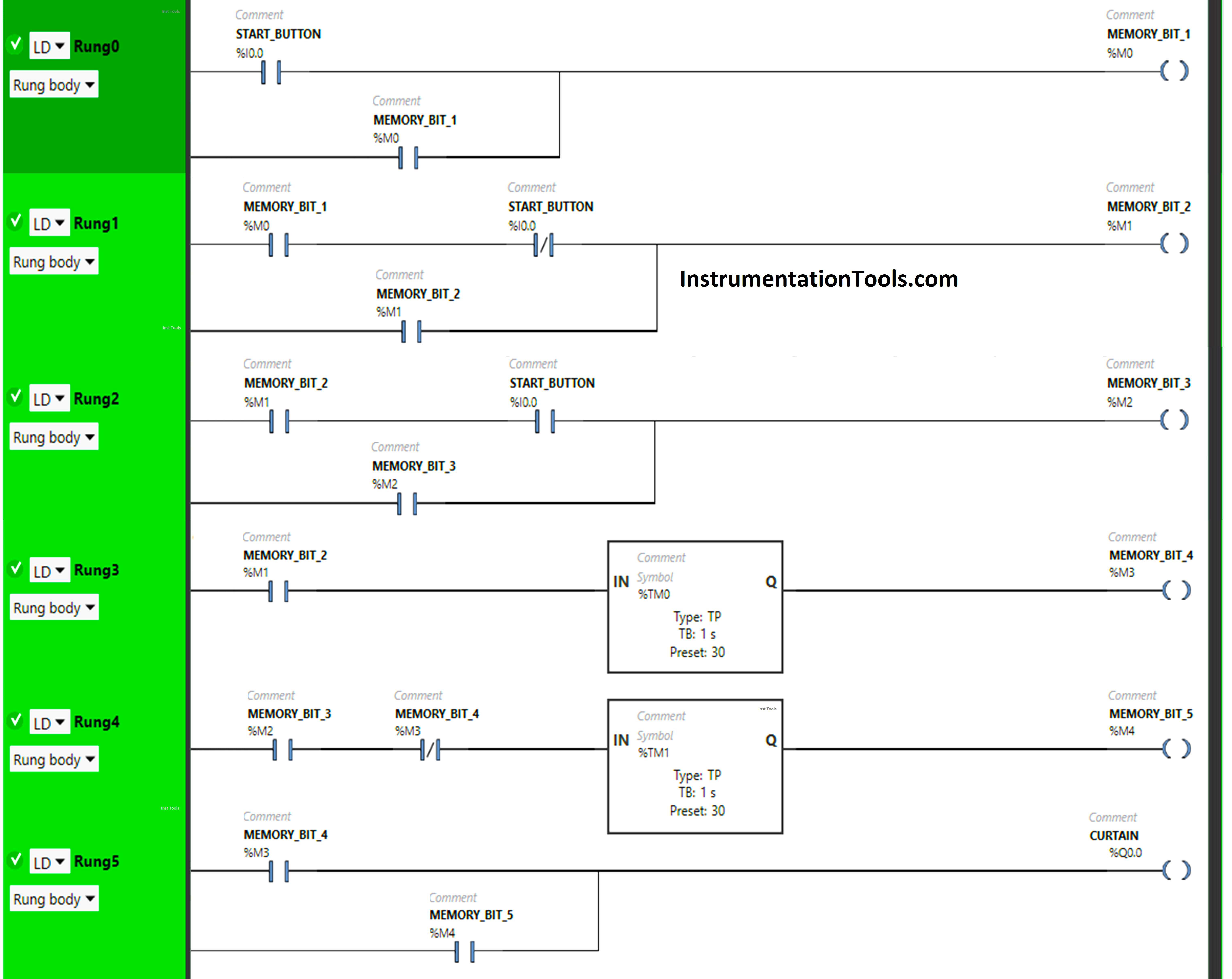
Program Description
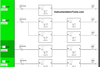
We have used Normally Open Contacts for Start Button(I0.0) and Memory Bits.
We have used Normally Closed Contacts for the Start Button (I0.0) and Memory Bit 4 (M3).
In Rung 0:
- Normally Open Contact is used for the Start Button(I0.0) to Turn ON Memory Bit 1 (M0).
- Memory Bit 1 (M0) is latched so that when the Start Button(I0.0) turns OFF, Memory Bit 1 (M0) still remains ON.
In Rung 1:
- Normally Open Contact is used for Memory Bit 1 (M0) to Turn ON Memory Bit 2 (M1).
- Normally Closed Contact is used for Start Button (I0.0) to Turn ON Memory Bit 2 (M1).
- Memory Bit 2 (M1) is latched so that when Memory Bit 1 (M0) turns OFF, Memory Bit 2 (M1) still remains ON.
In Rung 2:
- Normally Open Contacts are used for the Start Button (I0.0) and Memory Bit 2 (M1) to Turn ON Memory Bit 3 (M2).
- Memory Bit 3 (M2) is latched so that when the Start Button (I0.0) or Memory Bit 2 (M1) turns OFF, Memory Bit 3 (M2) still remains ON.
In Rung 3:
- Normally Open Contact is used for Memory Bit 2 (M1) to Turn ON Memory Bit 4 (M3).
- Timer TP is used to Turn ON Memory Bit 4 (M3) for a limited time.
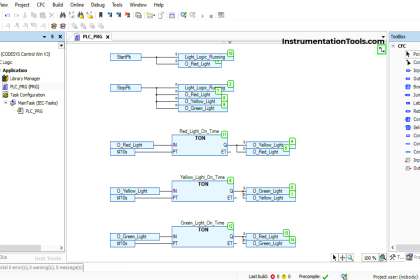
In Rung 4:
- Normally Open Contact is used for Memory Bit 3 (M2) to Turn ON Memory Bit 5 (M4).
- Normally Closed Contact is used to activate Memory Bit 4 (M3) to Turn ON Memory Bit 5 (M4).
- Timer TP is used to Turn ON Memory Bit 5 (M4) for a limited time.
In Rung 5:
- Normally Open Contact is used for Memory Bit 4 (M3) and Memory Bit 5 (M4) to Turn ON the output Curtain (Q0.0).
- Memory Bit 4 (M3) and Memory Bit 5 (M4) are connected in parallel, thus implementing OR Logic Gate.
Simulation of the PLC Program
Let’s simulate our PLC program and see the results. Please note that we may have shown only some part of the logic instead of the complete code. We recommend you to watch the above video to understand the program clearly.
When the Start Button is Pressed
When the Start Button (I0.0) is pressed and released, Memory Bit 1 (M0) turns ON and stores the data that the Start Button (I0.0) is pressed the first time as Memory bits store the data.
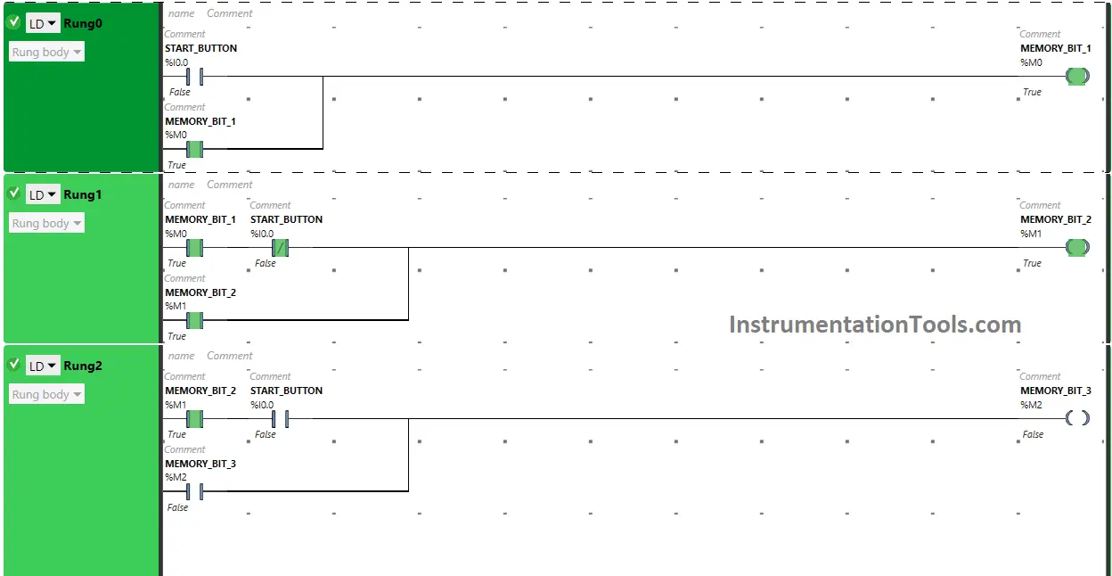
Memory Bit 1 (M0) is latched so that when the Start Button (I0.0) is released, Memory Bit 1 (M0) still remains ON.
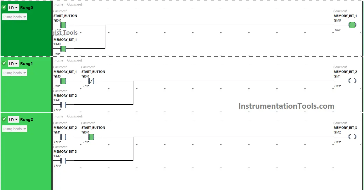
When Memory Bit 1 (M0) turns ON in Rung0, Normally Open Contact used for Memory Bit 1 (M0) in Rung1 will be in True State and will pass the signal to turn ON Memory Bit 2 (M1).
In a false state, Normally Closed Contact used for the Start Button (I0.0) also passes the signal and Memory Bit 2 (M1) will turn ON in Rung1. Memory Bit stores the data that the Start Button (I0.0) is released first time. Memory Bit 2 (M1) is latched so that when Memory Bit 1 (M0) turns OFF, Memory Bit 2 (M1) still remains ON.
When Memory Bit 2 (M1) turns ON in Rung1, Memory Bit 4 (M3) turns ON in Rung3 as Normally Open Contact used for Memory Bit 2 (M1) in Rung3 passes the signal to turn ON Memory Bit 4 (M3).
Memory Bit 4 ( M3) will remain ON for a limited time i.e. 30 seconds as Timer Function Block type TP is used to turn ON the Memory Bit 4 (M3) for a limited time.
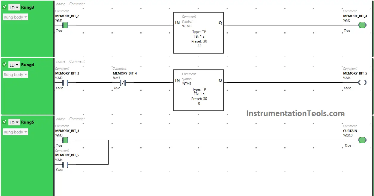
When Memory Bit 4 (M3) turns ON in Rung3, Normally Open Closed Contact used for Memory Bit 4 (M3) in Rung5 will be in True state and the Output Curtain (Q0.0) turns ON (Curtain Opens).
In Rung3, when Timer Function Block type TP reaches its set time i.e 30 seconds, Memory Bit 4 (M3) will turn OFF in both Rung3 and Rung5 and when Memory Bit 4 (M3) turns OFF in Rung5, the output Curtain (Q0.0) turns OFF ( Curtain Closes).
If the Start Button is Pressed again (Before the closure of Curtains)
When the Start Button (I0.0) is pressed and released again (Before Closure of Curtains) in Rung2, Normally Open Contacts used for both Memory Bit 2 (M1) and Start Button (I0.0) will pass the signal, and Memory Bit 3 (M2) will turn ON in both Rung2 and Rung4.
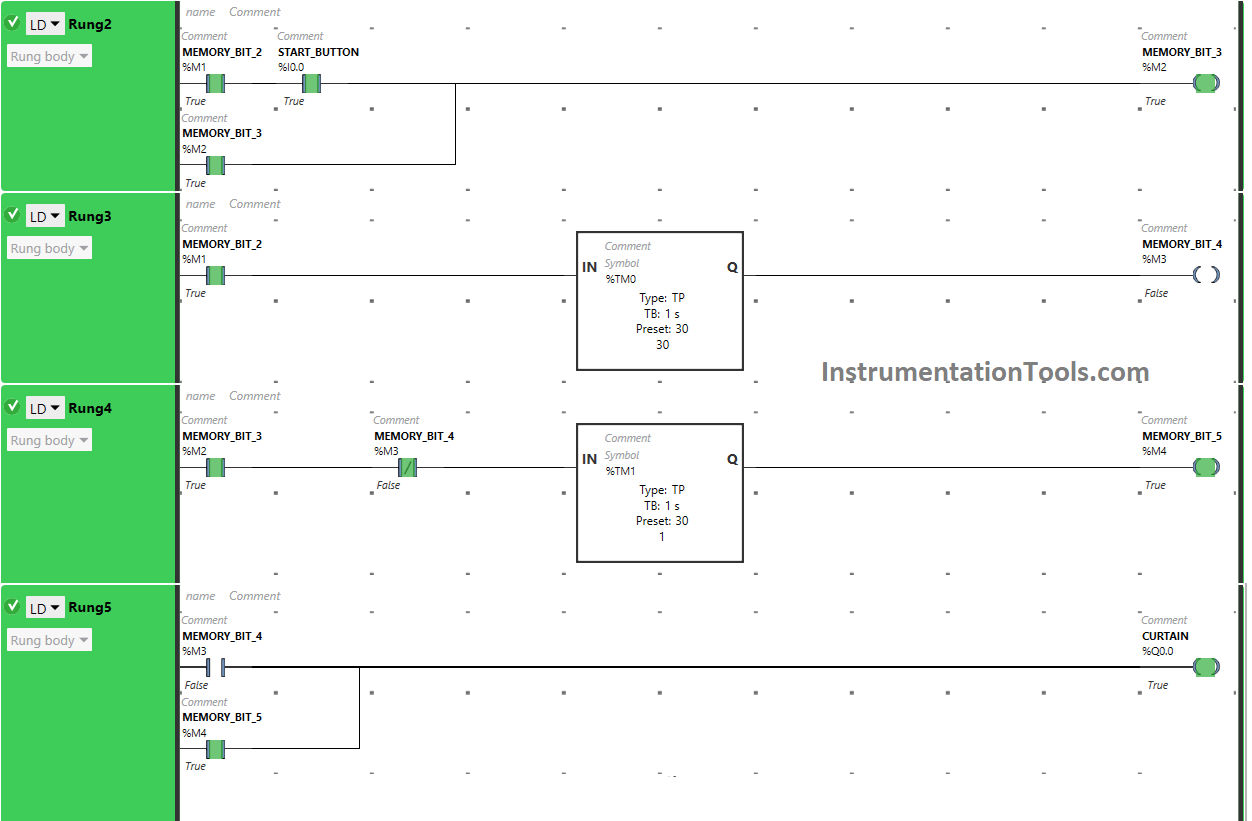
When Memory Bit 3 (M2) turns ON in Rung2, Memory Bit 5 (M4) turns ON in Rung4 as Normally Open Contact used for Memory Bit 3 (M2) in Rung4 passes the signal to turn ON Memory Bit 5 (M4).
In a false state, Normally Closed Contact used for Memory Bit 4 (M3) also passes the signal to turn ON Memory Bit 5 (M4). Memory Bit 5 ( M4) will remain ON for a limited time i.e. 30 seconds as Timer Function Block type TP is used to turn ON the Memory Bit 5 (M4) for a Limited time.
When Memory Bit 5 (M4) turns ON in Rung4, Normally Open Closed Contact used for Memory Bit 5 (M4) in Rung5 will be in True state and the Output Curtain (Q0.0) turns ON (Curtain Opens).
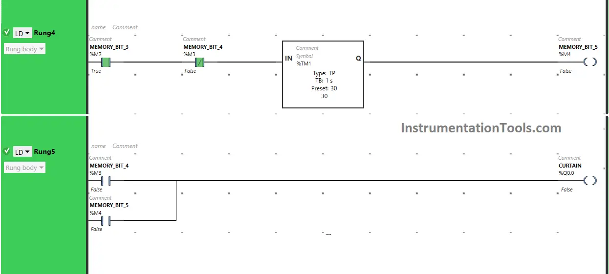
In Rung4, when Timer Function Block type TP reaches its set time i.e 30 seconds, Memory Bit 5 (M4) will turn OFF in both Rung4 and Rung5 and when Memory Bit 5 (M4) turns OFF in Rung5, the output Curtain (Q0.0) turns OFF ( Curtain Closes).
So, When the Start Button (I0.0) is pressed and released again (Before Closure of Curtains), the output Curtain (Q0.0) remains Open for an extra 30 seconds as in two Timer Function Block type TP is used.
Time is set to 30 seconds in both timers function blocks and when the Start Button (I0.0) is pressed the second time, the Timer starts in the second Timer function Block and the output Curtain (Q0.0) remains ON for extra 30 seconds i.e total of 60 seconds.
If you liked this article, please subscribe to our YouTube Channel for PLC and SCADA video tutorials.
You can also follow us on Facebook and Twitter to receive daily updates.
Read Next:
- PLC Program with 5-Second Floor Stops
- PLC Programming for Barrier Control
- Traffic Lights PLC Logic using Timers
- PLC Logic for Water Pumping System
- PLC Conveyor Forward and Reverse