Automatic Bottle Filling System is one of the example in PLC program using RSLOGIX 500.
Bottle Filling System

Problem Logic
Step Conditions:
- Start and Stop PB is used to start and stop the process.
- Start is pressed Conveyor starts moving until the Proximity Sensor is ON.
- Then solenoid valve is open for 5 seconds. After 5s Conveyor should start moving.
- The above process should continue unto 3 bottles.
- Process should continue still stop push button pressed.
List of Inputs and Outputs

PLC Program


Program Description
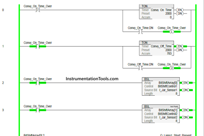
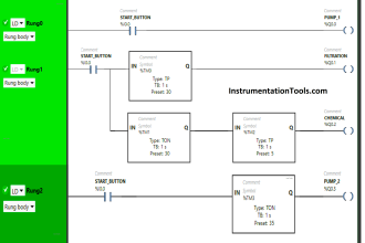
RUNG 0000
Latching rung to operate the system through Master Start and Stop PB.
RUNG 0001
To turn ON Conveyor motor, memory bit (B3:0/1 ) is used .
RUNG 0002
To turn on Conveyor motor using memory bit of start latching PB and B3:0/1, it will automatically turn off when B3:0/2 turns on once Proximity sensor activates.
Timer done is connected in parallel to turn conveyor motor ON again.
RUNG 0003
Proximity sensor output saved in memory bit to use in previous rung.
RUNG 0004 and Rung 0005
To store the status of proximity sensor B3:0/3 is used, Comparator block is used to compare counter accumulator value to stop the process once three bottle process had filled.
Rung 0006
To count the number of bottles, proximity sensor is given to up counter with preset value sets to 3.
RUNG 0007
Stop input is given to reset the counter.
Note:
- Memory bits are used to store the sensor output, since it is the simulation, sensor cannot turn off automatically.
- Memory bits are used to get the sequence of operation.
Conclusion:
The above explained simple bottle filling system is for example only. It may vary from real time.
If you liked this article, then please subscribe to our YouTube Channel for PLC and SCADA video tutorials.
You can also follow us on Facebook and Twitter to receive daily updates.
Read Next:
Allen Bradley Logical Operations
Gas Pressure Control using PLC


What is PB? several articles speak in this BP but I can not identify
Thanks.
Push button
Push button
PB stands for Push Button. Examples – Start push button, stop push button, etc.