Inst ToolsInst ToolsInst Tools
  • Ask
  • Courses
  • Videos
  • Q & A
    • Interview
      • Instrumentation
      • Electronics
      • Electrical
      • Practical Questions
    • MCQ
      • Instrumentation MCQ
      • Electrical MCQ
      • Electronics MCQ
      • Control Systems MCQ
      • Analog Electronics MCQ
      • Digital Electronics MCQ
      • Power Electronics MCQ
      • Microprocessor MCQ
      • Multiple Choice Questions
  • EE
    • Electronics
      • Electronics Q & A
      • Electronic Basics
      • Electronic Devices & Circuits
      • Electronics Animation
      • Digital Electronics
    • Electrical
      • Electrical Basics
      • Electrical Q & A
      • Power Electronics
      • Electrical Machines
      • Electrical Animation
      • Power Systems
      • Switchgear & Protection
      • Transmission & Distribution
  • Measure
    • Control Valves
    • Calibration
    • Temperature
    • Pressure
    • Flow
    • Level
    • Analyzers
    • Switches
    • Vibration
    • Solenoid Valve
  • Control
    • PLC Tutorials
    • Control Systems
    • Safety Instrumented System (SIS)
    • Communication
    • Fire & Gas System
  • More
    • Design
    • Tools
    • Animation
    • Basics
    • Formulas
    • Standards
    • TextBooks
    • Common
    • Software
    • Excel Tools
    • Erection & Commissioning
    • Process Fundamentals
    • Videos
    • Books
Search
All rights reserved. Reproduction in whole or in part without written permission is prohibited.
Reading: Applying Kirchhoff’s Voltage Law
Share
Notification Show More
Font ResizerAa
Inst ToolsInst Tools
Font ResizerAa
  • Courses
  • PLC Tutorials
  • Control Systems
Search
  • Ask
  • Courses
  • Videos
  • Q & A
    • Interview
    • MCQ
  • EE
    • Electronics
    • Electrical
  • Measure
    • Control Valves
    • Calibration
    • Temperature
    • Pressure
    • Flow
    • Level
    • Analyzers
    • Switches
    • Vibration
    • Solenoid Valve
  • Control
    • PLC Tutorials
    • Control Systems
    • Safety Instrumented System (SIS)
    • Communication
    • Fire & Gas System
  • More
    • Design
    • Tools
    • Animation
    • Basics
    • Formulas
    • Standards
    • TextBooks
    • Common
    • Software
    • Excel Tools
    • Erection & Commissioning
    • Process Fundamentals
    • Videos
    • Books
Follow US
All rights reserved. Reproduction in whole or in part without written permission is prohibited.
Inst Tools > Blog > Electrical Theory > Applying Kirchhoff’s Voltage Law

Applying Kirchhoff’s Voltage Law

Last updated: July 23, 2018 4:27 pm
Editorial Staff
Electrical Theory
No Comments
Share
3 Min Read
SHARE

Kirchhoff’s first law is also known as his “voltage law.” The voltage law gives the relationship between the “voltage drops” around any closed loop in a circuit, and the voltage sources in that loop. The total of these two quantities is always equal.

In equation form:

Kirchhoff’s Voltage Law

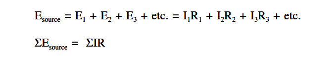
where the symbol Σ (the Greek letter sigma) means “the sum of.”

Kirchhoff’s voltage law can be applied only to closed loops (Figure 32). A closed loop must meet two conditions:

  1. It must have one or more voltage sources.
  2. It must have a complete path for current flow from any point, around the loop, and back to that point.

Closed Loop

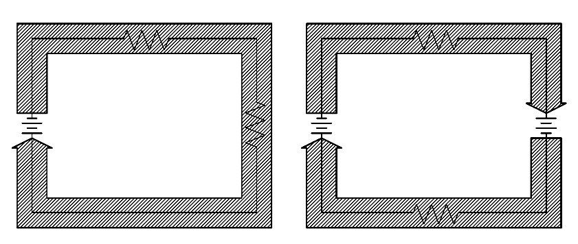
Figure 32 Closed Loop

You will remember that in a simple series circuit, the sum of the voltage drops around the circuit is equal to the applied voltage. Actually, this is Kirchhoff’s voltage law applied to the simplest case, that is, where there is only one loop and one voltage source.

Applying Kirchhoff’s Voltage Law

For a simple series circuit, Kirchhoff’s voltage law corresponds to Ohm’s Law. To find the current in a circuit (Figure 33) by using Kirchhoff’s voltage law, use below equation.

ΣEsource = Σ I R

Using Kirchhoff’s Voltage Law to find Current with one Source

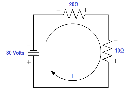
Figure 33 Using Kirchhoff’s Voltage Law to find Current with one Source

80 = 20 (I) + 10 (I)

80 = 30 (I)

I = 80/30 = 2.66 amps

In the problem above, the direction of current flow was known before solving the problem. When there is more than one voltage source, the direction of current flow may or may not be known. In such a case, a direction of current flow must be assumed in the beginning of the problem.

All the sources that would aid the current in the assumed direction of current flow are then positive, and all that would oppose current flow are negative. If the assumed direction is correct, the answer will be positive. The answer would be negative if the direction assumed was wrong. In any case, the correct magnitude will be attained.

For example, what is the current flow in Figure 34? Assume that the current is flowing in the direction shown.

Using Kirchhoff’s Voltage Law to find Current with Multiple Battery Sources

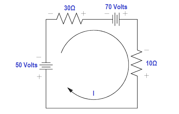
Figure 34 Using Kirchhoff’s Voltage Law to find Current with Multiple Battery Sources

Using Kirchhoff’s Voltage Law:

ΣEsource = Σ I R

50 – 70 = 30I + 10I

-20 = 40I

I = -20/40 = -0.5

The result is negative. The current is actually 0.5 ampere in the opposite direction to that of the assumed direction.

Don't Miss Our Updates
Be the first to get exclusive content straight to your email.
We promise not to spam you. You can unsubscribe at any time.
Invalid email address
You've successfully subscribed !
Voltmeters
Simplified Formulas for Parallel Circuit Resistance Calculations
4-Wire, Three-Phase Delta Wiring System
DC Machines Construction
Parallel Circuit
Share This Article
Facebook Whatsapp Whatsapp LinkedIn Copy Link
Share
Leave a Comment

Leave a Reply Cancel reply

Your email address will not be published. Required fields are marked *

Stay Connected

128.3kFollowersLike
69.1kFollowersFollow
208kSubscribersSubscribe
38kFollowersFollow

Categories

Recent Comments

  • Kamli on Top Free PLC Software
  • Guifty Shimica on Top Non-PLC Certification Courses for Automation Professionals
  • Guifty Shimica on Top Non-PLC Certification Courses for Automation Professionals
  • MIHARITSOA Aina Sitraka on Top Non-PLC Certification Courses for Automation Professionals

Related Articles

Voltage Polarities

Voltage Polarity and Current Direction

Circuit Breaker Control Circuit Wiring

Circuit Breaker Control Circuit

Units of Electrical Measurement

Units of Electrical Measurement

Motor Rotating Magnetic Field

AC Motor Theory

AC Generator Operation

Types of AC Generators

Ammeter with Shunt

Ammeter

Electrical Symbols

Electrical Symbols

Inductor Principle

Inductance and Inductive Reactance

More Articles

Industrial Sensors

Sensors Handbook

orifice plate vent hole

What is the Purpose of Orifice Plate Drain Hole and Vent Hole?

Direct Lift Diaphragm Normally Open Solenoid Valve

Types of Pilot Operated Diaphragm Solenoid Valve Principle

Causes of PLC Stop Mode

Various Causes for PLC Going in Stop Mode

Applications of Electrical Conduit System

What is an Electrical Conduit? – Types – How to Choose?

Bio Sensors Objective Questions

Bio Sensors Objective Questions

OPC Protocol

History of OPC Protocol

Process Override Switch

What is Process Override Switch (POS)?

Follow US
All rights reserved. Reproduction in whole or in part without written permission is prohibited.
Welcome Back!

Sign in to your account

Username or Email Address
Password

Lost your password?