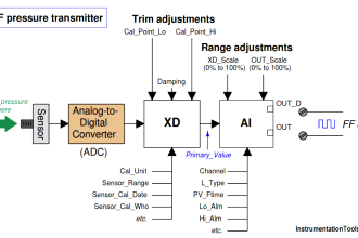
This article explains the process of displaying analog input data from the PLC to the Weintek MT6071iE HMI via RS232 serial communication. In this system, an analog voltage signal ranging from 0 to 10V (adjusted using a potentiometer) is read through the PLC’s analog input port. The data is then processed using the RD3A instruction to convert it into a 12-bit digital value (ranging from 0 to 4095). The resulting data is displayed on the HMI by accessing the appropriate word memory address in the PLC.
Required Devices
1. FX3U-14MT Lollette PLC
This PLC is a compact unit based on the Mitsubishi FX3U series and manufactured as a compatible version by Lollette. It is equipped with 8 digital inputs, 6 transistor outputs (sink type), 4 analog inputs (0–10 V), and 2 analog outputs. The device operates on a 24 VDC power supply and features an RS-232 DB9 serial communication port with a default baud rate of 38.4 kbps. It is suitable for prototyping, simulation, or small-scale automation learning. However, since it is not an official Mitsubishi product, it is not recommended for certified industrial control systems or environments that require high reliability.
2. EasyBuilder Pro Software
EasyBuilder Pro is a software developed by Weintek for designing graphical interfaces on HMI devices, such as indicators, buttons, charts, and alarms. In addition to interface design, the software is used to configure HMI communication settings with PLCs, including protocol type, baud rate, parity, and register addresses. EasyBuilder Pro supports a wide range of communication protocols, including Mitsubishi FX series over RS232 and RS485.
3. Weintek MT6071iE HMI
This HMI is a 7-inch touchscreen device with a resolution of 800×480 pixels. It supports serial communication through RS-232 (COM1) and RS-485 (COM2 & COM3) ports, along with USB connections (mini USB and USB host). The device can be used to read from and write to various PLC types, including Mitsubishi FX3U. It also supports program transfer via USB or Ethernet (if available).
4. GX Works2 Software
GX Works2 is the official software from Mitsubishi Electric used for programming, configuring, and monitoring MELSEC series PLCs such as FX3U and FX5U. It supports a wide range of instructions, including basic logic (LD, OUT), analog functions (like RD3A), and serial communication. The software also provides offline simulation and online monitoring functions for real-time system diagnostics.
5. DB9 RS-232 Male to Female Cable
This cable is used for serial communication between the PLC and HMI. The male end (pin) connects to the RS-232 port on the FX3U-14MT PLC, while the female end (socket) connects to COM1 (RS-232) on the Weintek HMI. The cable length should not exceed 15 meters to maintain stable signal quality and avoid electrical noise interference.
How To Map Mitsubishi Analog Inputs?
In the video below, we tested the potentiometer as analog input in PLC and shown the respective analog values on the HMI using RS232.
Initial Preparation
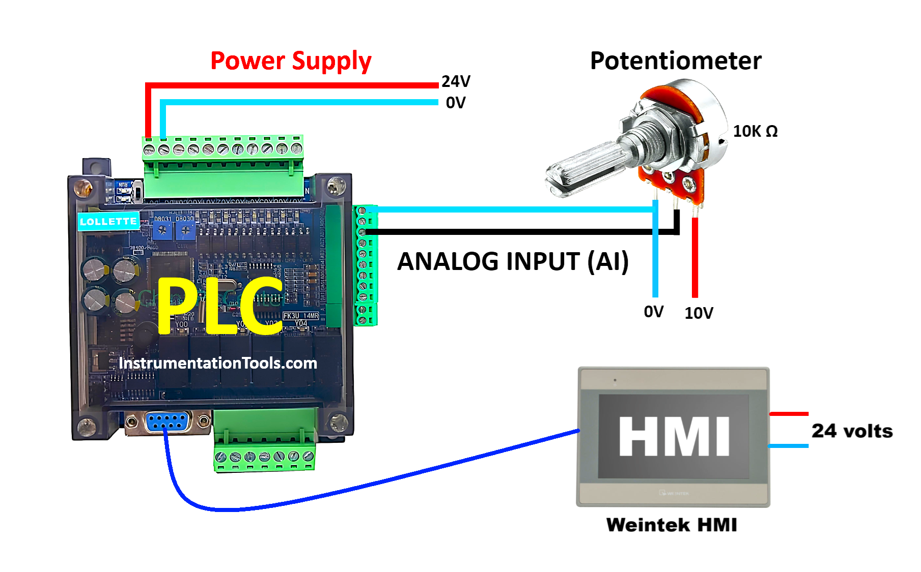
1. Power Supply Setup
Connect a 24 V DC external power source to the FX3U-14MT PLC.
2. PLC-to-PC Communication
Connect the PLC to a computer using an RS232 to USB serial cable. Ensure the cable is compatible with the DB9 serial port on the PLC.
Analog Input Configuration on FX3U-14MT PLC
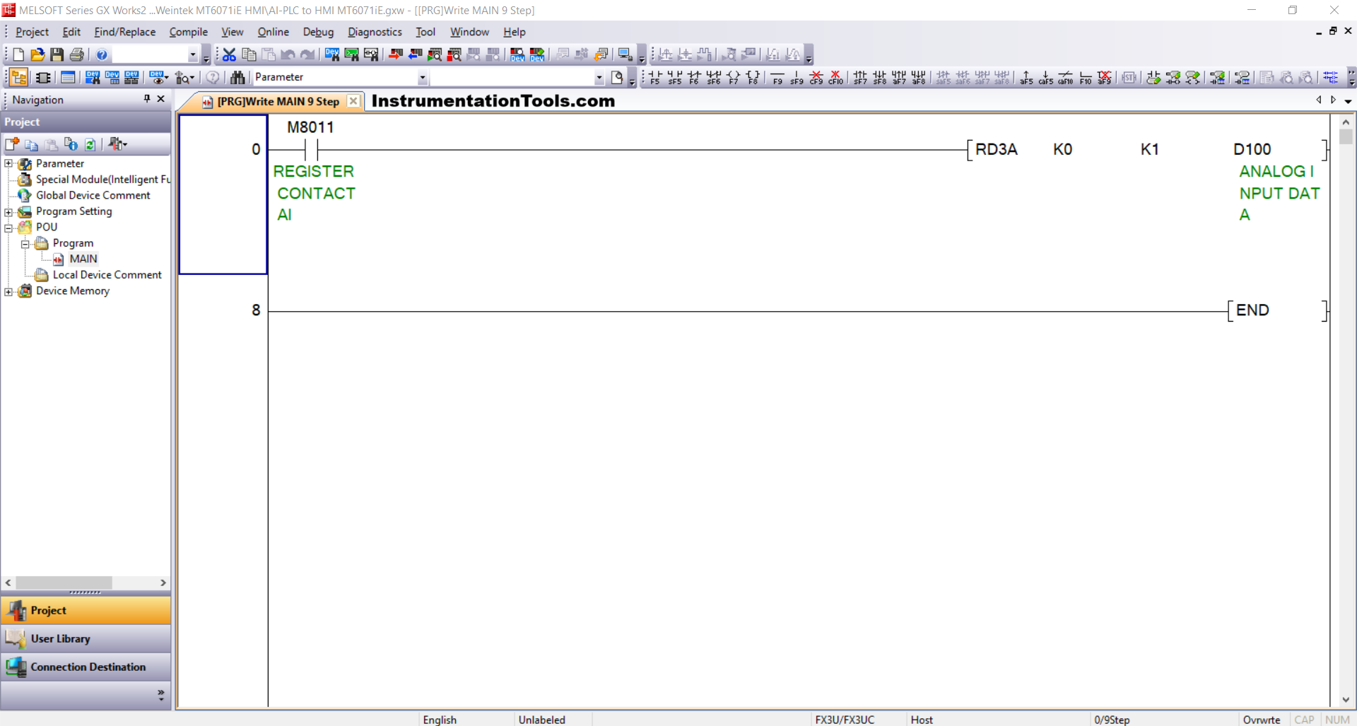
1. Programming with GX Works2
Create a program in GX Works2 using the RD3A instruction to read analog input values from the PLC’s input channels.
- Module Configuration: Use parameter 0/K0 to reference the internal analog module.
- Analog Input Channel: Specify the input channel to be read, for example, 1/K1.
- Data Storage Address: The analog reading will be stored in word memory (D100) ANALOG INPUT DATA.
- Instruction Trigger: Use a Normally Open (NO) contact from system bit M8011 as the trigger condition for executing RD3A. The M8011 bit turns ON automatically every 250 ms, making it suitable for periodic reading.
2. Device Connection Verification
Ensure the USB to RS-232 converter is connected and recognized by the operating system.
Open Device Manager on your computer and identify the active COM port (e.g., COM5).
Confirm that the serial communication parameters are set as follows:
- Baud Rate: 38400 bps
- Data Bits: 7
- Parity: Even
- Stop Bit: 1
3. Communication Settings in GX Works2
Configure the communication interface in the software to connect with the PLC:
Go to Connection Detection → select Connection1
Set the following parameters:
- Interface: Serial USB (RS-232C)
- COM Port: Match the detected port (e.g., COM5)
- Transmission Speed: 38.4 Kbps
- Data Bits / Parity / Stop Bits: 7 / Even / 1
Run the Connection Test and ensure the message “Successfully Connected with the FX3U/FX3UC CPU” appears.
4. Program Transfer to PLC
Once the connection is verified:
- Navigate to Online → Write to PLC
- Select Parameter + Program to upload all the configuration and logic
- Click Execute to transfer the program to the PLC memory. Wait for the process to complete without errors.
Designing the HMI Interface Using EasyBuilder Pro
1. Connecting HMI to the Computer
Power on the Weintek MT6071iE HMI with a 24 VDC supply. Connect it to the PC using a Mini USB Type B cable for programming and project transfer.
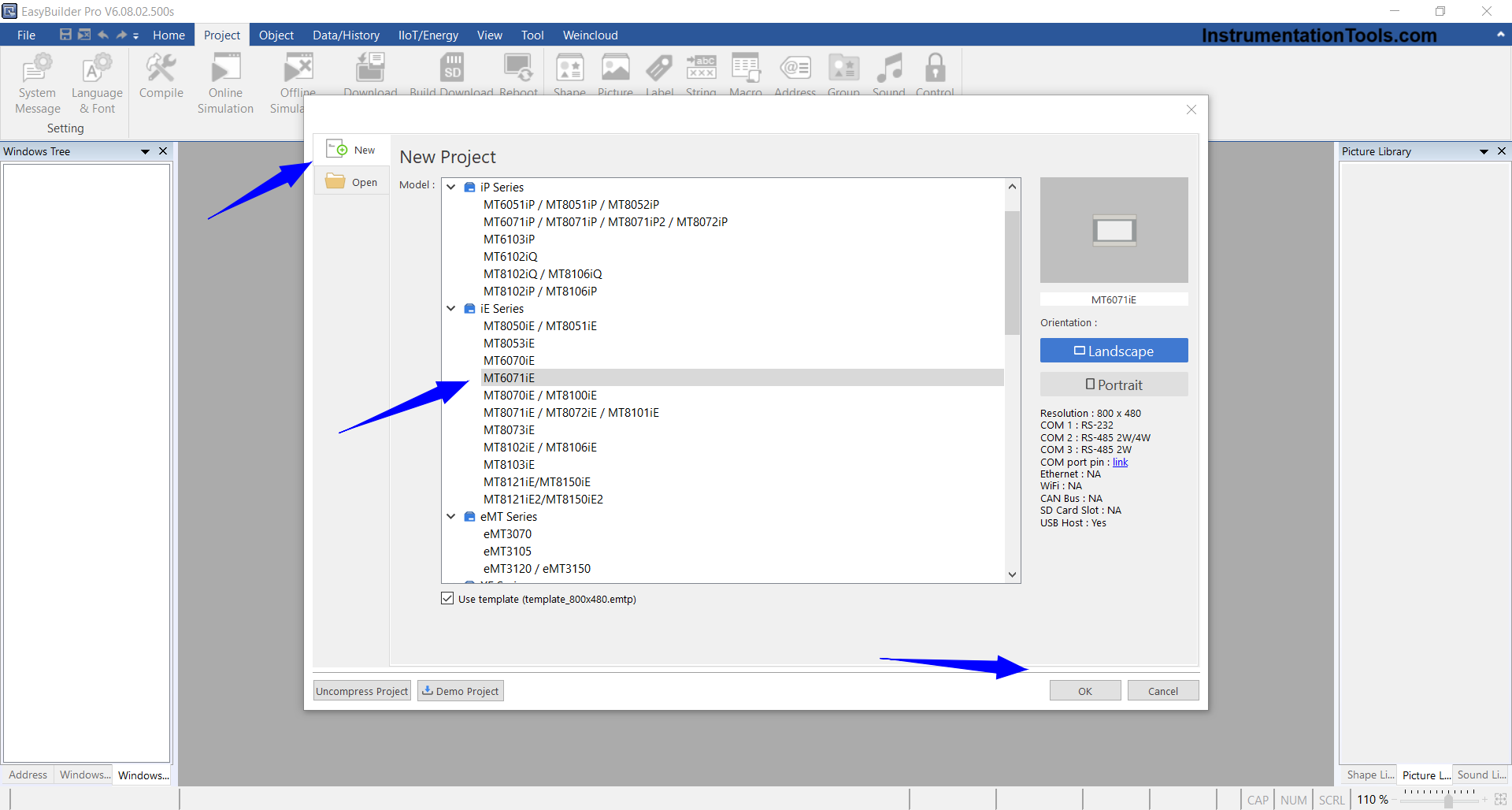
2. Creating a New Project in EasyBuilder Pro
Launch EasyBuilder Pro and:
- Click New Project
- Select device type: MT6071iE
- Click OK to enter the project workspace
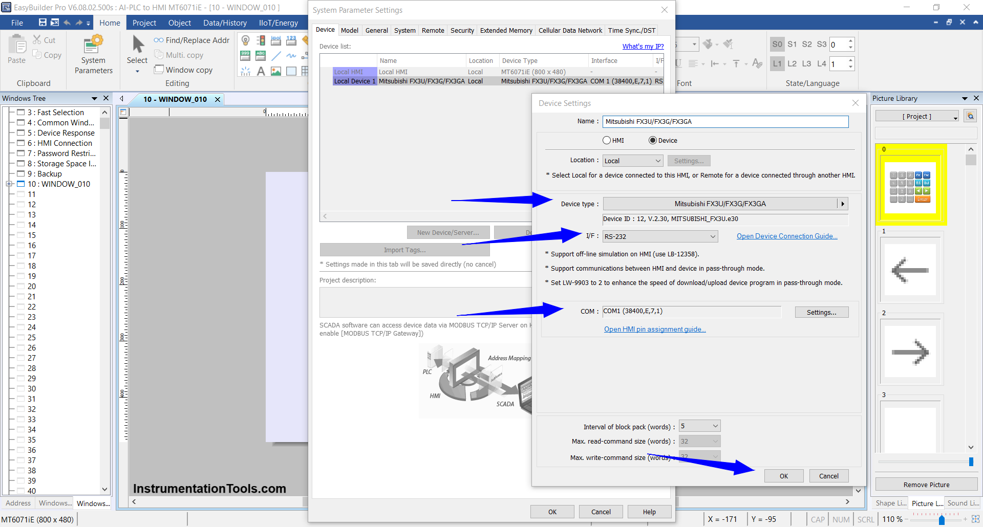
3. Adding the PLC Device
Set up communication between the HMI and PLC via the System Parameter Settings window:
Click New Device/Server
Configure the parameters:
- Port: RS-232
- COM Port: COM1(*)
- Baud Rate & Format: 38400 bps,
- Parity: Even, Data Bits: 7, Stop Bit:1
- Device Type: Mitsubishi FX3U/FX3G/FX3GA
Click OK to save settings
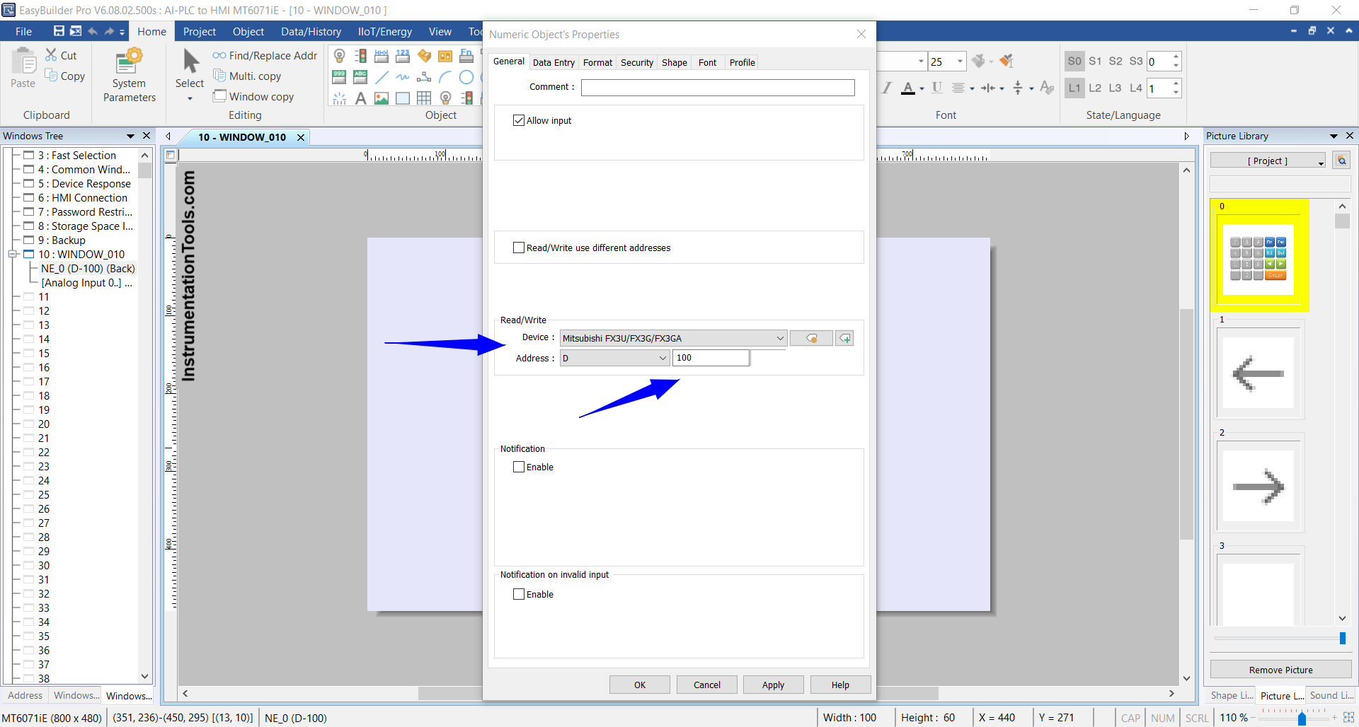
4. Designing the HMI Interface
Add display objects to show analog data from the PLC:
Go to Object → Numeric Display
Set the following:
- Device: Mitsubishi FX3U/FX3G/FX3GA
- Address: D100 (match the PLC’s analog input word memory address)
- Data Format: 16-bit Unsigned
Click OK to place the object on the HMI screen.
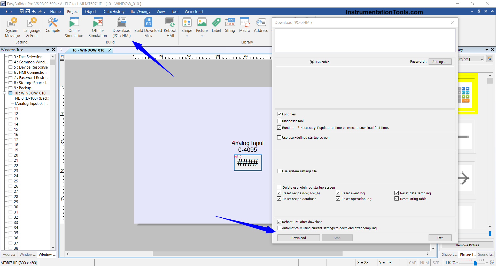
5. Downloading the Project to the HMI
Once the design is complete:
- Go to Project → Download (PC → HMI)
- Ensure the HMI is still connected to the PC via USB
- The project will be transferred from the computer to the HMI
6. Connecting HMI to PLC
After the download process is complete:
Disconnect the Mini USB Type B cable from the HMI
Connect the HMI to the PLC using a DB9 RS-232 Male to Female serial cable:
- Male end to the RS-232 port on the PLC
- Female end to COM1 on the HMI
With this setup, the HMI will be able to display real-time analog input data from the PLC via RS-232 serial communication.
Read Next:
- Read Mitsubishi PLC Analog Input and Display in HMI
- Mitsubishi PLC + Weintek HMI: Analog Output
- PLC Program for Glass Cutting and Polishing Machine
- Elevator Control PLC Program with Floor Stop
- Analog Voltage Control in PLC Using Weintek HMI