Inst ToolsInst ToolsInst Tools
  • Courses
  • Videos
  • Q & A
    • Interview
      • Instrumentation
      • Electronics
      • Electrical
      • Practical Questions
    • MCQ
      • Instrumentation MCQ
      • Electrical MCQ
      • Electronics MCQ
      • Control Systems MCQ
      • Analog Electronics MCQ
      • Digital Electronics MCQ
      • Power Electronics MCQ
      • Microprocessor MCQ
      • Multiple Choice Questions
  • EE
    • Electronics
      • Electronics Q & A
      • Electronic Basics
      • Electronic Devices & Circuits
      • Electronics Animation
      • Digital Electronics
    • Electrical
      • Electrical Basics
      • Electrical Q & A
      • Power Electronics
      • Electrical Machines
      • Electrical Animation
      • Power Systems
      • Switchgear & Protection
      • Transmission & Distribution
  • Measure
    • Control Valves
    • Calibration
    • Temperature
    • Pressure
    • Flow
    • Level
    • Analyzers
    • Switches
    • Vibration
    • Solenoid Valve
  • Control
    • PLC Tutorials
    • Control Systems
    • Safety Instrumented System (SIS)
    • Communication
    • Fire & Gas System
  • More
    • Design
    • Tools
    • Animation
    • Basics
    • Formulas
    • Standards
    • TextBooks
    • Common
    • Software
    • Excel Tools
    • Erection & Commissioning
    • Process Fundamentals
    • Videos
    • Books
Search
All rights reserved. Reproduction in whole or in part without written permission is prohibited.
Reading: Pressure Transmitters Leg Compensation Technique
Share
Notification Show More
Font ResizerAa
Inst ToolsInst Tools
Font ResizerAa
  • Courses
  • PLC Tutorials
  • Control Systems
Search
  • Courses
  • Videos
  • Q & A
    • Interview
    • MCQ
  • EE
    • Electronics
    • Electrical
  • Measure
    • Control Valves
    • Calibration
    • Temperature
    • Pressure
    • Flow
    • Level
    • Analyzers
    • Switches
    • Vibration
    • Solenoid Valve
  • Control
    • PLC Tutorials
    • Control Systems
    • Safety Instrumented System (SIS)
    • Communication
    • Fire & Gas System
  • More
    • Design
    • Tools
    • Animation
    • Basics
    • Formulas
    • Standards
    • TextBooks
    • Common
    • Software
    • Excel Tools
    • Erection & Commissioning
    • Process Fundamentals
    • Videos
    • Books
Follow US
All rights reserved. Reproduction in whole or in part without written permission is prohibited.
Inst Tools > Blog > Level Measurement > Pressure Transmitters Leg Compensation Technique

Pressure Transmitters Leg Compensation Technique

Last updated: August 28, 2019 8:16 pm
Editorial Staff
Level Measurement
1 Comment
Share
6 Min Read
SHARE

Alternative to Pressure Transmitters Leg Compensation

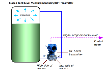
An alternative to using a compensating leg to subtract gas pressure inside an enclosed vessel is to simply use a second pressure transmitter and electronically subtract the two pressures in a computing device:

Two pressure transmitters

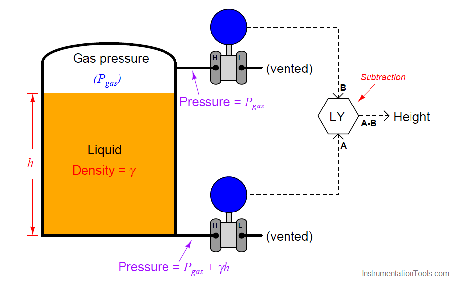
This approach enjoys the distinct advantage of avoiding a potentially wet compensating leg, but suffers the disadvantages of extra cost and greater error due to the potential calibration drift of two transmitters rather than just one. Such a system is also impractical in applications where the gas pressure is substantial compared to the hydrostatic (elevation head) pressure.

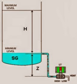
If we add a third pressure transmitter to this system, located a known distance (x) above the bottom transmitter, we have all the pieces necessary for what is called a tank expert system. These systems are used on large storage tanks operating at or near atmospheric pressure, and have the ability to measure infer liquid height, liquid density, total liquid volume, and total liquid mass stored in the tank:

tank expert system

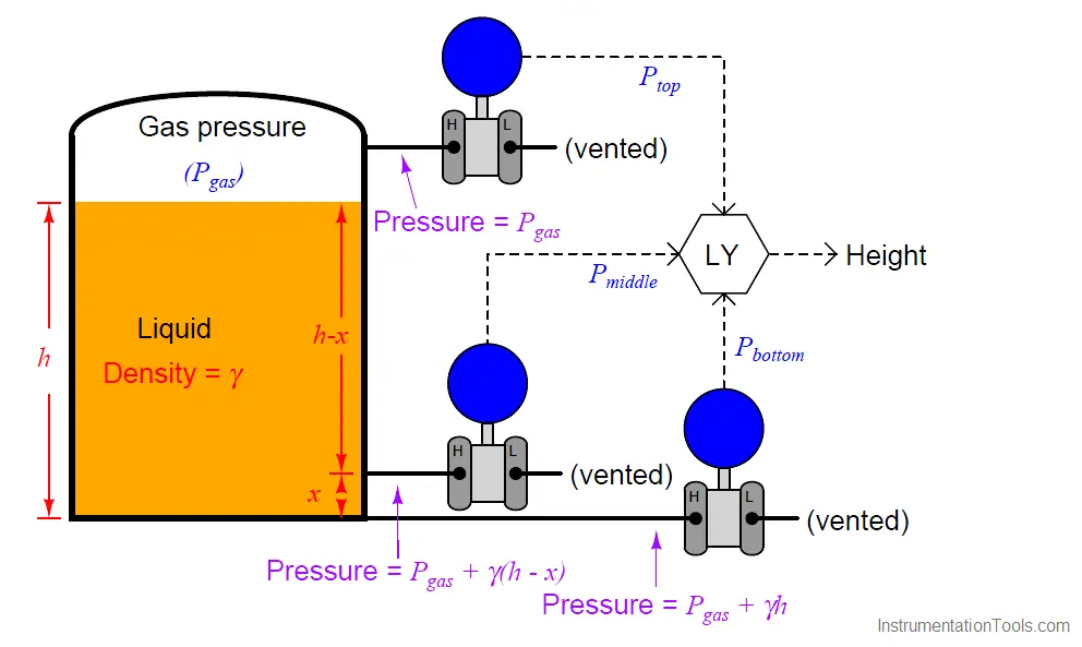
The pressure difference between the bottom and middle transmitters will change only if the liquid density (Note 1 ) changes, since the two transmitters are separated by a known and fixed height difference.

Note 1 : Assuming the liquid level is equal to or greater than x. Otherwise, the pressure difference between Pbottom and Pmiddle will depend on liquid density and liquid height. However, this condition is easy to check: the level computer simply checks to see if Pmiddle and Ptop are unequal. If so, then the computer knows the liquid level exceeds x and it is safe to calculate density. If not, and Pmiddle registers the same as Ptop, the computer knows those two transmitters are both registering gas pressure only, and it knows to stop calculating density.

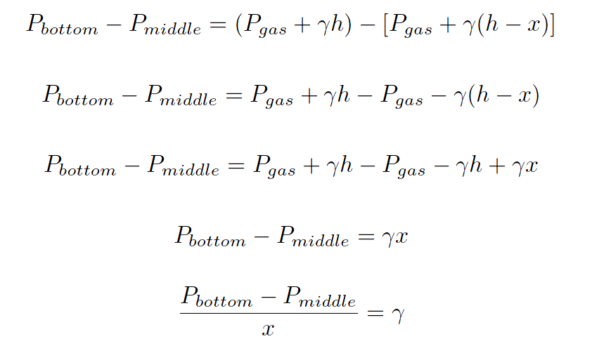
Algebraic manipulation shows us how the measured pressures may be used by the level computer (LY) to continuously calculate liquid density (γ):

Pressure Transmitter Calculations

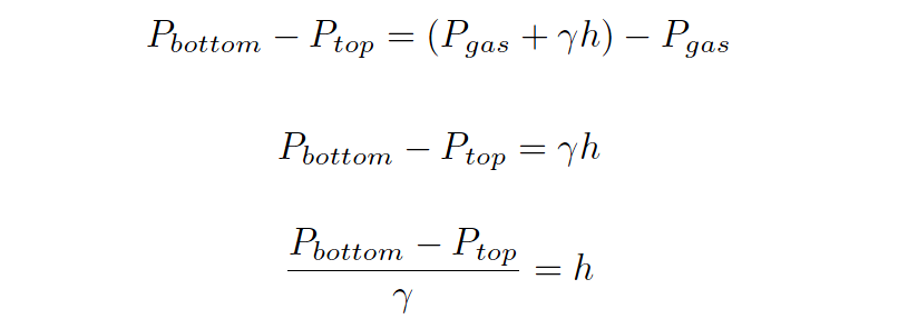
Once the computer knows the value of γ, it may calculate the height of liquid in the tank with great accuracy based on the pressure measurements taken by the bottom and top transmitters:

Pressure Transmitter Calculations - 2

With all the computing power available in the LY, it is possible to characterize the tank such that this height measurement converts to a precise volume measurement (V ), which may then be converted into a total mass (m) measurement based on the mass density of the liquid (ρ) and the acceleration of gravity (g). First, the computer calculates mass density based on the proportionality between mass and weight (shown here starting with the equivalence between the two forms of the hydrostatic pressure formula):

ρgh = γh

ρg = γ

ρ = γ/g

Armed with the mass density of the liquid inside the tank, the computer may now calculate total liquid mass stored inside the tank:

m = ρV

Dimensional analysis shows how units of mass density and volume cancel to yield only units of mass in this last equation:

[kg] =  [ kg/m3 ] m3

Here we see a vivid example of how several measurements may be inferred from just a few actual process (in this case, pressure) measurements. Three pressure measurements on this tank allow us to compute four inferred variables: liquid density, liquid height, liquid volume, and liquid mass.

The accurate measurement of liquids in storage tanks is not just useful for process operations, but also for conducting business. Whether the liquid represents raw material purchased from a supplier, or a processed product ready to be pumped out to a customer, both parties have a vested interest in knowing the exact quantity of liquid bought or sold.

Measurement applications such as this are known as custody transfer, because they represent the transfer of custody (ownership) of a substance exchanged in a business agreement. In some instances, both buyer and seller operate and maintain their own custody transfer instrumentation, while in other instances there is only one instrument, the calibration of which validated by a neutral party.

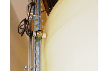
A photograph showing the two lower pressure transmitters of a tank expert system on a refrigerated butane storage vessel appears here:

Tanks Pressure Transmitter

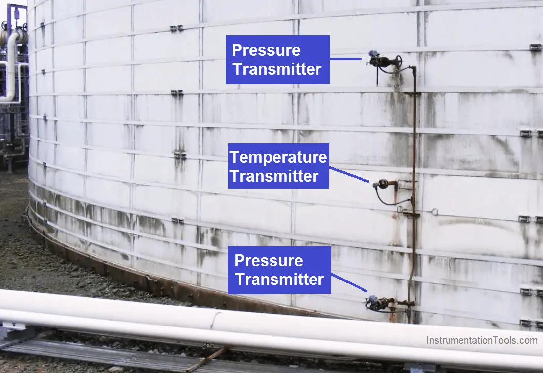
The upper and lower instruments are pressure transmitters, while the middle instrument is a temperature sensor used to report the temperature of the refrigerated butane to the control system.

 Credits : Tony R. Kuphaldt – Creative Commons Attribution 4.0 License

Don't Miss Our Updates
Be the first to get exclusive content straight to your email.
We promise not to spam you. You can unsubscribe at any time.
Invalid email address
You've successfully subscribed !

Recommended Articles

Hydrostatic Level Measurement
Open and Closed Tank Level Calculations
Advantages & Disadvantages of Level Measurement Systems
Capacitance Level Switch Working Principle
Level Measurement with Dry leg and Installed Below Tapping Point
Float level switch Principle
Share This Article
Facebook Whatsapp Whatsapp LinkedIn Copy Link
Share
1 Comment
  • Tim Klunk says:
    April 7, 2020 at 7:23 pm

    Most excellent article, very well written, showing great methods.

    Reply

Leave a Reply Cancel reply

Your email address will not be published. Required fields are marked *

Stay Connected

128.3kFollowersLike
69.1kFollowersFollow
208kSubscribersSubscribe
38kFollowersFollow

Categories

Recent Comments

  • William Snyder on Top Non-PLC Certification Courses for Automation Professionals
  • Kamli on Top Free PLC Software
  • Guifty Shimica on Top Non-PLC Certification Courses for Automation Professionals
  • Guifty Shimica on Top Non-PLC Certification Courses for Automation Professionals

Related Articles

level-transmitter-calibration-procedure

Level Transmitter Calibration Procedure

Magnetostrictive instruments

Magnetostrictive Level Measurement

Capillary Remote Seal Leave Measurement

Siemens Pressure Transmitter with Remote Seals Calculations

Dip Tape

What is Dip Tape Level Measurement?

Asymmetric capillary for Level Measurement

Effects of Symmetric and Asymmetric Capillary Tube Pressure Measurement

DP-Level-Transmitter-Diaphragm-with-capillary-tube-type

DP Level Transmitter Calibration for Diaphragm Seal with Capillary

Radar Level Transmitter in Briddle level Measurement

Radar Level Transmitter in Briddle level Measurement

Slop Tank Level Transmitter Erection

Wrong Installation of Horn Type Radar Level Transmitter on Sloping Tank

More Articles

Why are Impulse Lines often Installed in a Sloping Manner (Angle)

Why are Impulse Lines often Installed in a Sloping Manner?

High Voltage and Power System Stability Interview Questions

High Voltage and Power System Stability Interview Questions

Power Electronics Objective Questions

Thyristors Mock Test

Troubleshooting Magnetic Flow Meters Common Problems

Troubleshooting Magnetic Flow Meters Common Problems

How to Read an Electrical Wiring Diagram

How to Read an Electrical Wiring Diagram?

Transistor Amplifier Working Principle

Abbreviations of Pressure, Temperature & Flow

Abbreviations of Pressure, Temperature & Flow

Absorption Chiller Principle - HVAC System

HVAC Double Effect Absorption Chiller

Follow US
All rights reserved. Reproduction in whole or in part without written permission is prohibited.
Welcome Back!

Sign in to your account

Username or Email Address
Password

Lost your password?