The single-acting spring return cylinder:
These are just like the standard single-acting cylinders with the exception that they have a spring inside of them. At the completion of the power stroke, the spring helps to push the piston back to its initial starting position.
The double-acting cylinder:
It is called double-acting because the cylinder has a power stroke on the push and pull. This type of double-acting cylinder is used primarily for mechanical devices.
Basic Calculations:
The Area is calculated by using basic algebra with regard to the bore.
To get the area we take half the bore and square it after that multiply it by Pi.
Once we know the area we multiply it by the pressure to get the force.
Formula for Force = Area x Pressure Area = (1/2 Bore) ^2 x Pi
The equation to determine how much gas from a tank: P1 x V1 = P2 x V2
Note: This formula is known as Boyle’s Law, which states “The volume of a given mass of gas is inversely proportional to the absolute pressure if the temperature remains constant”.
Let us assume for the moment that the temperature does remain constant.
P1 = input pressure
V1 = input volume.
P2 i= output pressure
V2 = output volume.
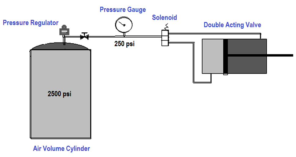
Example 1:
A 88 cubic inch HPA tank with a 2500 psi tank pressure, 250 psi regulated pressure, and a double-acting cylinder with a 4″ bore and a 6″ throw with a 1″ rod to actuate a mechanical device.
Let us find out how much-compressed air is in the tank.
P1 x V1 = P2 x V2
2500 x 88 = 250 x V2
220000 = 250 x V2
220000 / 250 = V2
V2 = 880 cubic inches, at 250 psi
Example 2:
Using the example above, find out how much volume is in the cylinder using the formula
Volume = Area (bore) x Length (throw).
The Push Stroke V = ((1/2 bore)^2 x Pi) x throw
V = ((1/2 4)^2 x Pi) x 6
V = (2^2 x Pi) x 6
V = 12.56 x 6 V
= 75.36 cubic inches
The Pull Stroke Vrod = ((.5)^2 x Pi) x 6 Vrod = 4.71 cubic inches
V = 75.36 (The Push Stroke V) – 4.71(The Pull Stroke Vrod) = 70.65 cubic inches
The total volume for the push, stroke (75.36), pull stroke (70.65)
If we add them together to get 146.01 cubic inches.
If we divide that number into the available volume that the tank has: Force = Area x Pressure
and we know that we have an area = 12.56 square inches on the face of the piston in the ‘push’ stroke
The area is equal to (12.56 – 0.785) = 11.775 square inches on the face of the piston in the ‘pull stroke.
The Push Force = 12.56 x 250.
The Pull Force = 11.775 x 250
Read Next:
- Control Valve Sizing
- Types of Valve Actuators
- Relation between Cv and Kv
- Types of Failures in Valves
- Control Valve Stroke Test


I understand that the air consumption for a single pull and a single push stroke is calculated. Adding them we get consumption a single cycle. This article is very helpful for design Engineers.