In industrial automation, a thorough knowledge of communication topologies is a must. So, the programmer should also know the various failure conditions of that topology, so that they can be well versed with various troubleshooting ideas.
Industrial Communication Topology Based Failures
Because if the communication fails, then it ultimately affects the reliability, uptime, and stability of the plant operation. And as data is nowadays communicated in a large manner in the cloud services for IoT, identifying potential topological failure is a must. In this post, we will see various industrial communication topology-based failures.
Line topology failures
Let us start with the most basic and simple topology, which is line topology. In line topology, all the devices are connected in a single and straight line, all looped with each other from device – 1 to device – N. It requires minimum cabling, is easy to understand and lay, and is popular in small-scale and less critical applications.
Now, if a single cable in the network breaks, then the whole communication breaks, which is the biggest drawback of this topology. Apart from this, if there is even a loose terminal connection or if a device is off, then the communication will break. But this also has a theory. Let us assume the following sequence – PLC to VFD-1 to VFD-2 to VFD-3.
Here, if an issue occurs in any device apart from the PLC, like a power outage, then the PLC will communicate with the other devices. But if the terminals are shorted in any device, then the whole line will break. If any one device catches up electrical noise, then the whole line will be disrupted. And if any loose connection exists in one device, then the preceding devices will not communicate following the natural line flow, thus not affecting the preceding devices.
If the topology has a termination resistance in the end, and if it is absent, or of a wrong value, or present at the end of more than one device apart from just the last one, then the communication will not happen.
If the cable length is running too high, then signal reflections will occur, or communication will make and break frequently, or random CRC errors will occur.
Star topology
Next, let us see one of the most popular schemes – the star topology. As the name suggests, all the devices communicate with a single central device. So, this central device will be like a stem spreading branches for other devices. It is easy to expand, has simple troubleshooting, and has a good performance overall.
The biggest failure here is the central device. If it fails, then the whole network fails. But if one device fails due to a power failure or a loose connection, then only that device will be bypassed from communication. Mostly, this topology starts with Ethernet communication in industries.
So, if the Ethernet hub switch from where the cables are distributed fails, then the communication will break for the whole line. And if the switch used is managed, and configured with wrong settings like misconfiguration, flooding of multicast or broadcast packets being sent by any one device, or incorrect port settings, then too the failure happens for the whole line, either in make and break, or fully.
Ring topology
This topology tries to eradicate the drawbacks of the line and star by making a ring of the devices. As the name implies, all the devices will be connected in a ring. Due to this, each device will have two communication paths to share data from. In normal conditions, one link is logically blocked, and the network behaves like a line. When a fault occurs, the ring reconfigures automatically, and the blocked paths are restored through alternate paths.
This network reconfiguration is normal for communication protocols that are not too fast and demand quick uptime restoration. For those opposite protocols, which are critical for machine applications, if a time lag is there for reconnection, then the system might get disrupted for some time. The issue occurs if one device fails completely here. Due to this, the devices before and after this device will now become the endpoints, and communication will continue. Now, if one side link faults due to some issue, then the redundant communication will not happen, because one path is already broken.
In a ring topology, the network can heal itself only if the redundancy protocol is configured correctly. One device in the ring must act as the ring manager (or supervisor), whose job is to intentionally block one communication path during normal operation and continuously monitor the ring’s health. All other devices behave as ring clients and simply forward data. If the ring manager is not configured, or if more than one device is configured as the ring manager, the network does not know which path to block or open.
As a result, Ethernet loops occur, causing excessive duplicate packets and network flooding. In some cases, the ring never switches to the alternate path when a cable breaks, and instead of healing, the entire network becomes unstable or completely unresponsive. This is why a ring may appear to work normally during commissioning, but fail badly the moment a cable is unplugged or a device is powered off.
Tree topology
As the name implies, it is an actual tree-like structure, where the central device distributes its branches into a corresponding sub-central device, and they then distribute further down, thus forming a branch of networks with its independent head. This is a modern approach and is used in large-scale applications, due to scalability, clear separation of responsibilities, easier traffic management, and support for security zoning.
If a particular network fails, then only that network is affected. But if a central (higher-level) device fails in a tree topology, the entire downstream chain (branch or whole plant) will break, because the topology is hierarchical. Each lower level depends completely on the level above it for communication beyond its local scope. So when a central node fails, everything below it becomes isolated.
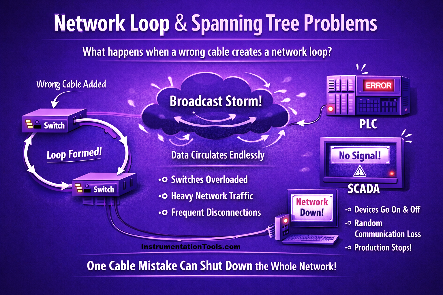
In a tree topology, problems can happen when an extra network cable is connected by mistake, creating a loop between switches. Because Ethernet does not know where to stop sending data, the same messages keep circulating in the network again and again. This creates heavy network traffic, also called a broadcast storm, which overloads the switches.
If Spanning Tree Protocol (STP) is not configured correctly or reacts too slowly, it cannot block the extra path in time. As a result, PLCs, HMIs, and SCADA systems start losing communication randomly, devices appear and disappear, or sometimes the entire network stops working, even though all hardware looks healthy. These failures are dangerous because a small wiring mistake can shut down a whole production line within seconds.