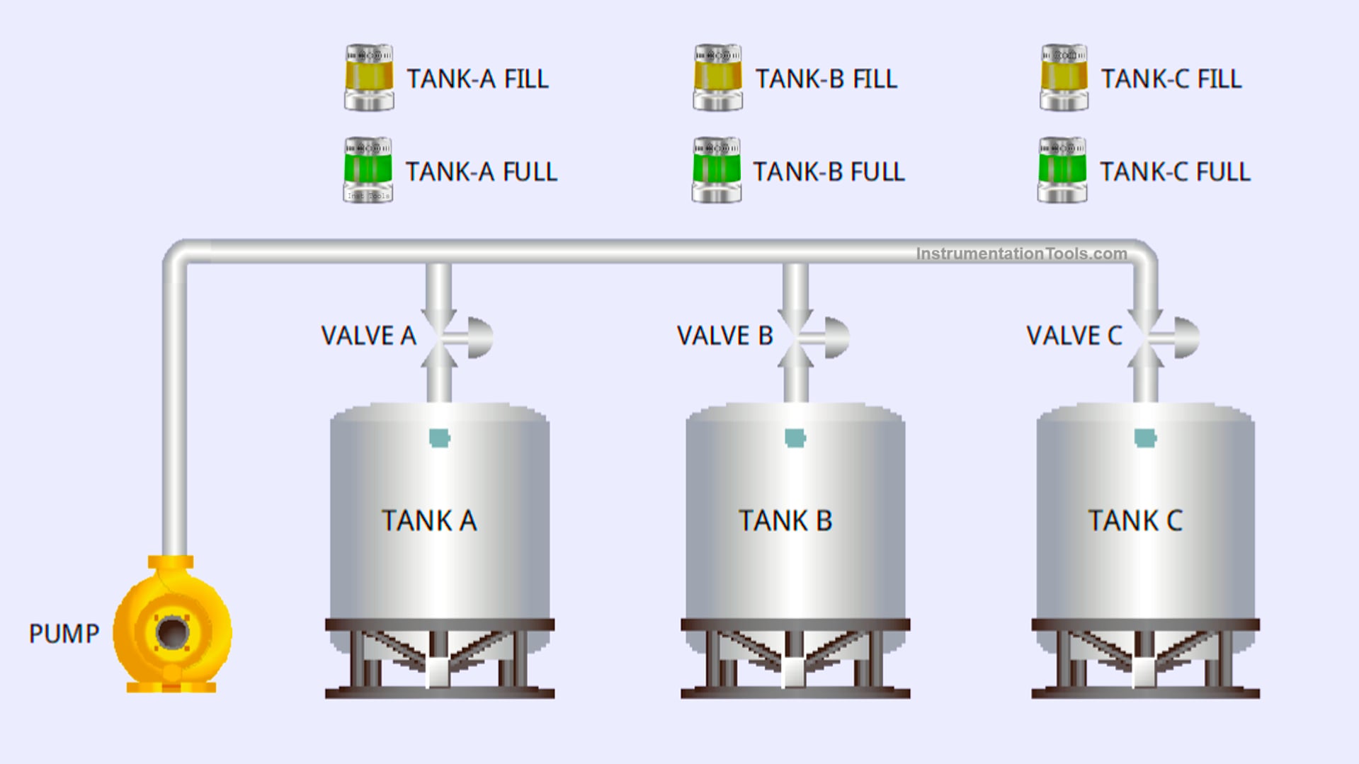
This article discusses a Liquid Level Control with Priority logic using Siemens PLC. The system is designed to control the liquid levels in multiple storage tanks by applying priority-based control logic. With this system, the liquid flow is directed to specific tanks according to the predetermined priority levels. The PLC system monitors the liquid level in each tank and controls the valves to manage the filling process or stop the liquid flow. The system is equipped with alarm indicators to provide alerts during the filling process or when a tank has reached its full capacity.
Program Objective
System Steps
- Initialization:
- The system starts by measuring the initial liquid level in each tank.
- Tank priorities are determined based on order (Tank A has the highest priority, followed by Tank B, and lastly Tank C).
- Tank Filling Process:
- If the liquid level in Tank A falls below the minimum level, the system will open the valve to Tank A and activate the pump.
- When the liquid level in Tank A reaches the maximum threshold, the valve to Tank A will close, and the system will proceed to fill Tank B or Tank C if needed.
- The pump will be activated 3 seconds after a valve is opened.
- Priority Logic:
- Tanks with higher priority will be filled first.
- If more than one tank has a liquid level below the minimum level, filling will be carried out sequentially based on the predefined priority order.
- Filling Process Termination:
- The system will turn off the pump and close all valves if all tanks have reached the maximum liquid level.
- Alarm Indicator:
- Each tank is equipped with an alarm indicator to provide alerts during the filling process or when the tank has reached its full capacity.
Mapping Details
| S.No. | Comment | Input (I) | Output (Q) | Memory Bit | Memory Word | Timers |
|---|---|---|---|---|---|---|
| 1 | PB_START | I0.0 | ||||
| 2 | PB_STOP | I0.1 | ||||
| 3 | VALVE_TANKA | Q0.0 | ||||
| 4 | VALVE_TANKB | Q0.1 | ||||
| 5 | VALVE_TANKC | Q0.2 | ||||
| 6 | PUMP | Q0.3 | ||||
| 7 | TANKA_FILL | Q0.4 | ||||
| 8 | TANKA_FULL | Q0.5 | ||||
| 9 | TANKB_FILL | Q0.6 | ||||
| 10 | TANKB_FULL | Q0.7 | ||||
| 11 | TANKC_FILL | Q1.0 | ||||
| 12 | TANKC_FULL | Q1.1 | ||||
| 13 | PV_TANKA | MW0 | ||||
| 14 | PV_TANKB | MW1 | ||||
| 15 | PV_TANKC | MW2 | ||||
| 16 | SYSTEM_ON | M3.0 | ||||
| 17 | TIMER_PUMP | DB1 |
Priority-Based Liquid Level Control
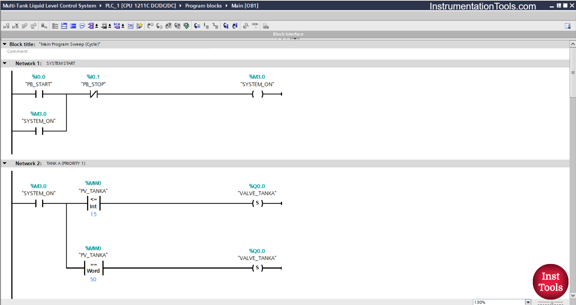
NETWORK 1 (SYSTEM START)
In this network, when the PB_START (I0.0) button is Pressed, the memory bit SYSTEM_ON (M3.0) will be in the HIGH state. Because it uses Latching, even though the PB_START (I0.0) button has been Released the memory bit SYSTEM_ON (M3.0) will remain in the HIGH state.
The memory bit SYSTEM_ON (M3.0) will be in the LOW state if the PB_STOP (I0.1) button is Pressed.
NETWORK 2 (TANK A (PRIORITY 1))
In this network, when the NO contact of the memory bit SYSTEM_ON (M3.0) is in the HIGH state and the value of the memory word PV_TANKA (MW0) is Less Than Or Equal To “15”, then the VALVE_TANKA (Q0.0) output will be OPEN.
When the NO contact of the memory bit SYSTEM_ON (M3.0) is in the HIGH state and the value of the memory word PV_TANKA (MW0) is Equal To “50”, then the output VALVE_TANKA (Q0.0) will be CLOSED.
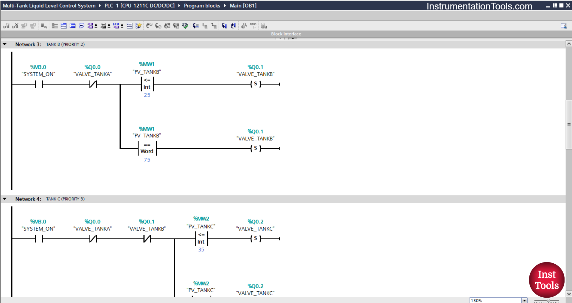
NETWORK 3 (TANK B (PRIORITY 2))
In this network, if contact NO of the memory bit SYSTEM_ON (M3.0) is in the HIGH state and the value of the memory word PV_TANKB (MW1) is Less Than Or Equal To “25”, then the output VALVE_TANKB (Q0.1) will be OPEN.
When the NO contact of the bit memory bit SYSTEM_ON (M3.0) is in the HIGH state and the value of the word memory PV_TANKB (MW1) is Equal To “75” or if the NC contact of the output VALVE_TANKA (Q0.0) is in the HIGH state, then the output VALVE_TANKB (Q0.1) will be CLOSED.
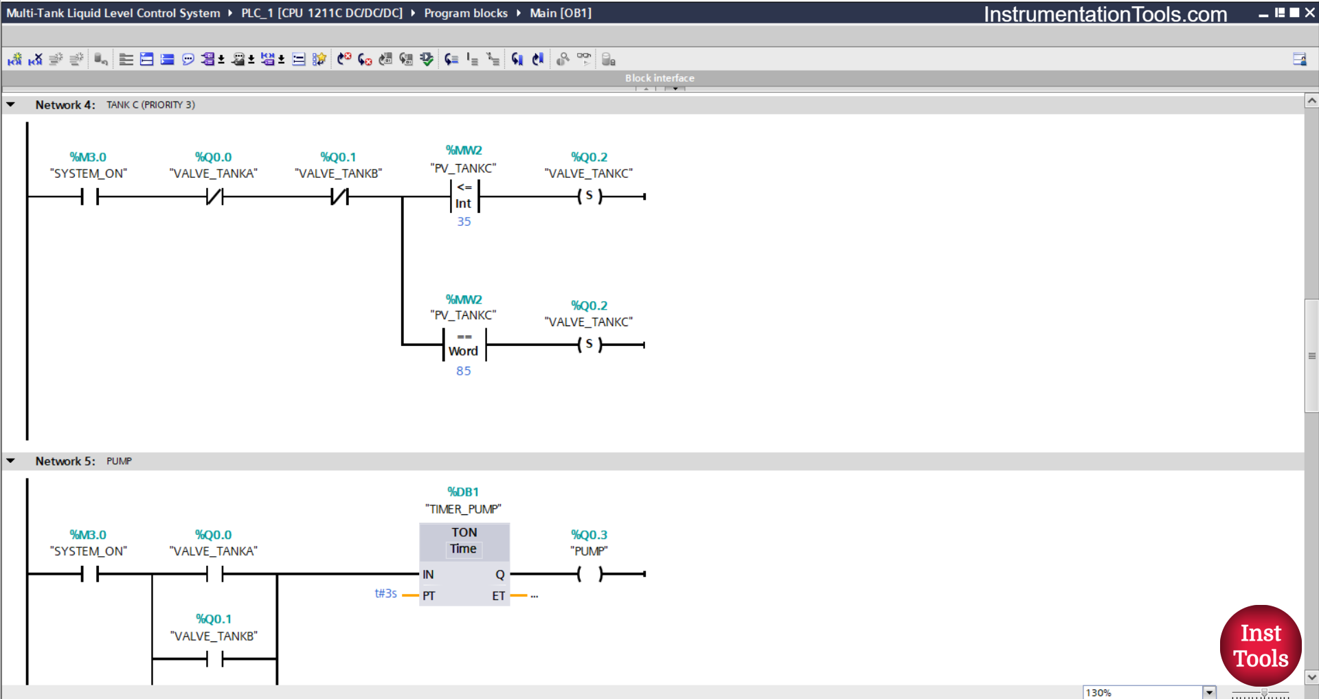
NETWORK 4 (TANK C (PRIORITY 3))
In this network, if the NO contact of the memory bit SYSTEM_ON (M3.0) is in the HIGH state and the value of the memory word PV_TANKC (MW2) is Less Than Or Equal To “35”, then the VALVE_TANKC (Q0.2) output will be OPEN.
When the NO contact of the memory bit SYSTEM_ON (M3.0) is in the HIGH state and the value of the memory word PV_TANKC (MW2) is Equal To “85”, then the output VALVE_TANKC (Q0.2) will be CLOSED.
Or, if the NC contact of the VALVE_TANKA (Q0.0) or VALVE_TANKB (Q0.1) output is in the HIGH state, then the VALVE_TANKC (Q0.2) output will be CLOSED.
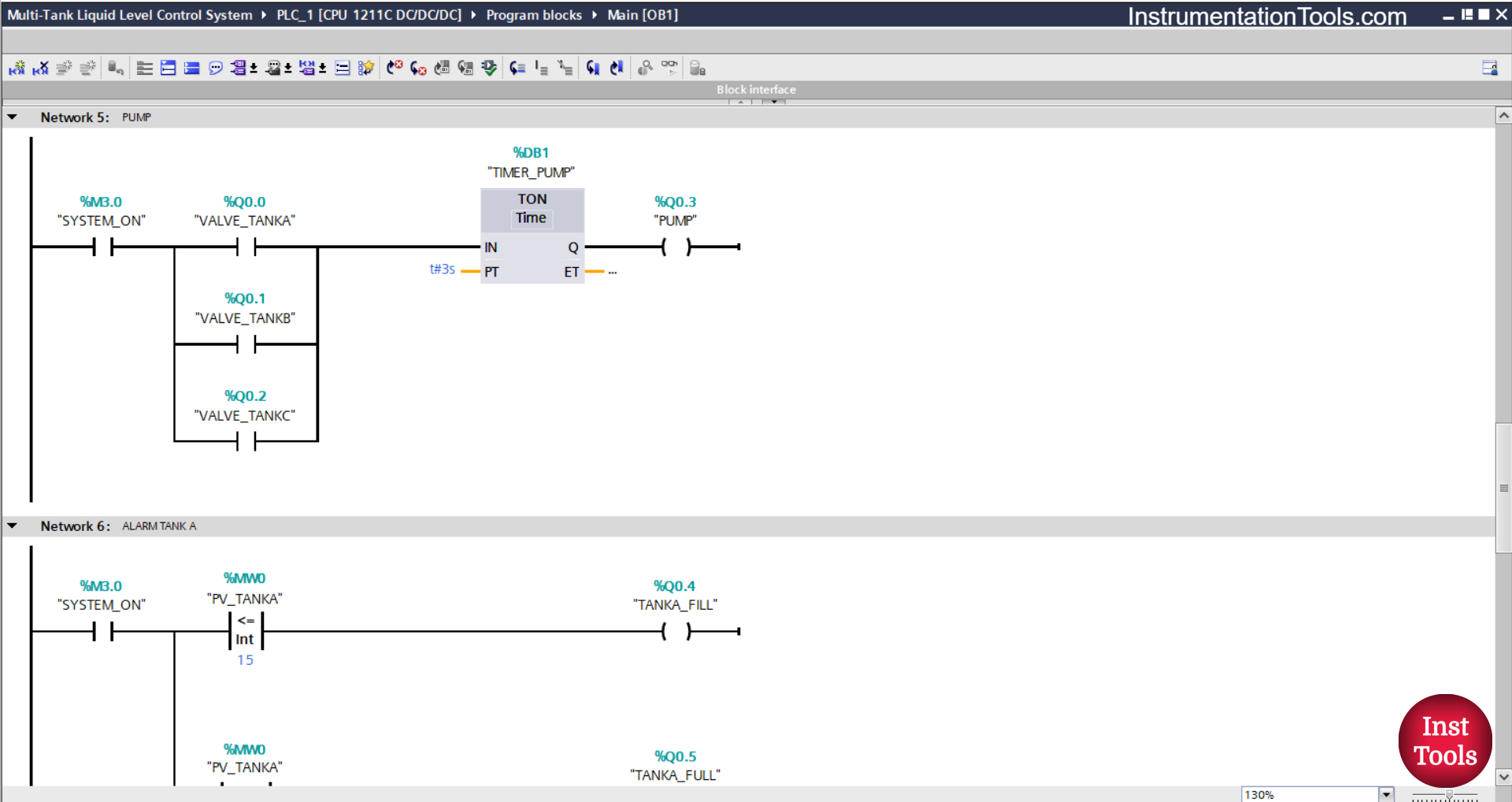
NETWORK 5 (PUMP)
The TIMER_PUMP (DB1) timer will start counting up to 3 seconds when the NO contact of the memory bit SYSTEM_ON (M3.0) in the HIGH state and one of the NO contacts VALVE_TANKA (Q0.0), VALVE_TANK C(Q0.2), and VALVE_TANKB (Q0.1) output in the HIGH state.
After the Timer TIMER_PUMP (DB1) finishes counting, the output PUMP (Q0.3) will become ON.
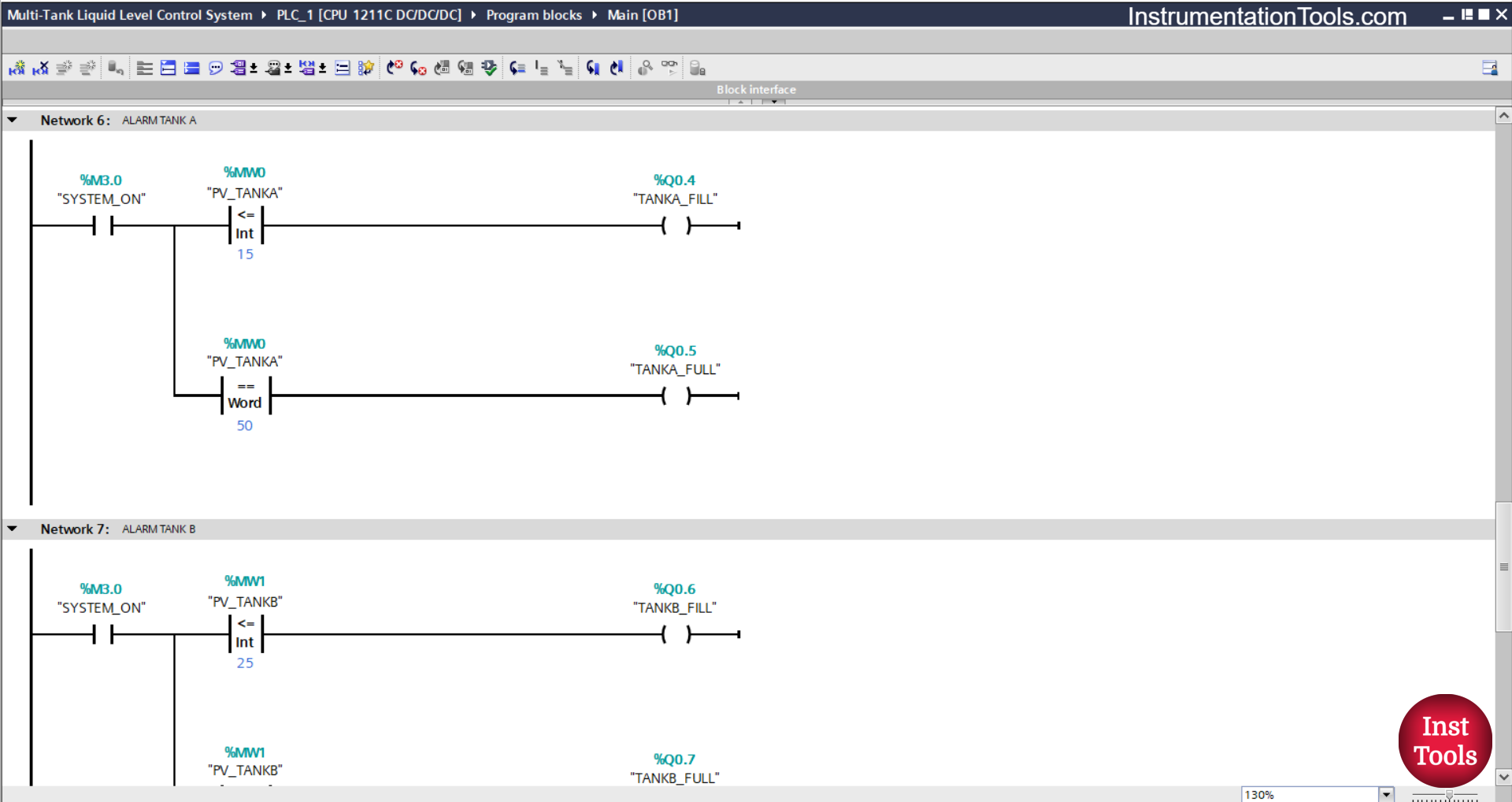
NETWORK 6 (TANK ALARM A)
In this network, when the NO contact of the memory bit SYSTEM_ON (M3.0) is in the HIGH state and the value of the memory word PV_TANKA (MW0) is Less Than Or Equal To “15”, then the TANKA_FILL (Q0.4) output will be ON.
And, when the NO contact of the memory bit SYSTEM_ON (M3.0) in the HIGH state and the value of the memory word PV_TANKA (MW0) is Equal To “50”, then the TANKA_FULL (Q0.5) output will be ON.
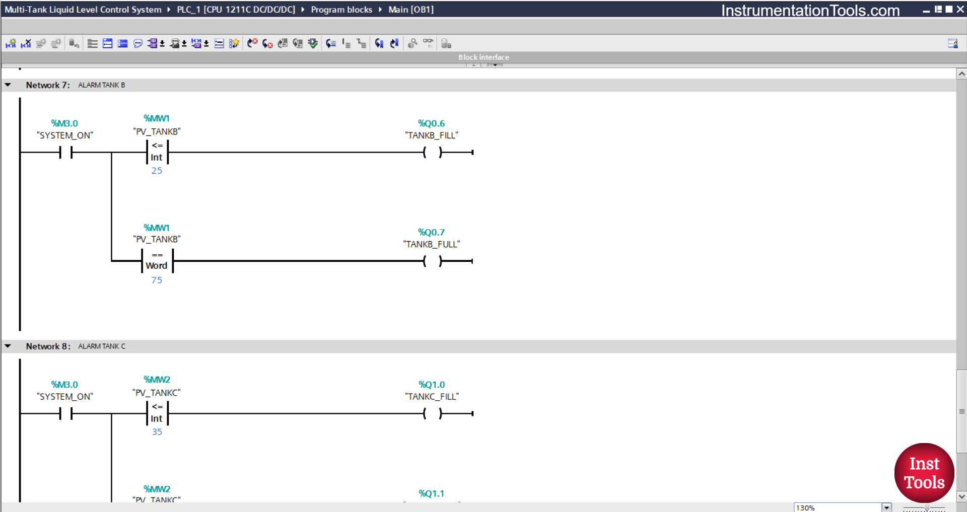
NETWORK 7 (TANK B ALARM)
In this network, when the NO contact of the memory bit SYSTEM_ON (M3.0) is in the HIGH state and the value of the memory word PV_TANKB (MW1) is Less Than Or Equal To “25”, then the output TANKB_FILL (Q0.6) will be ON.
And, if the NO contact of the memory bit SYSTEM_ON (M3.0) in the HIGH state and the value of the memory word PV_TANKB (MW1) is Equal To “75”, then the output TANKB_FULL (Q0.7) will be ON.
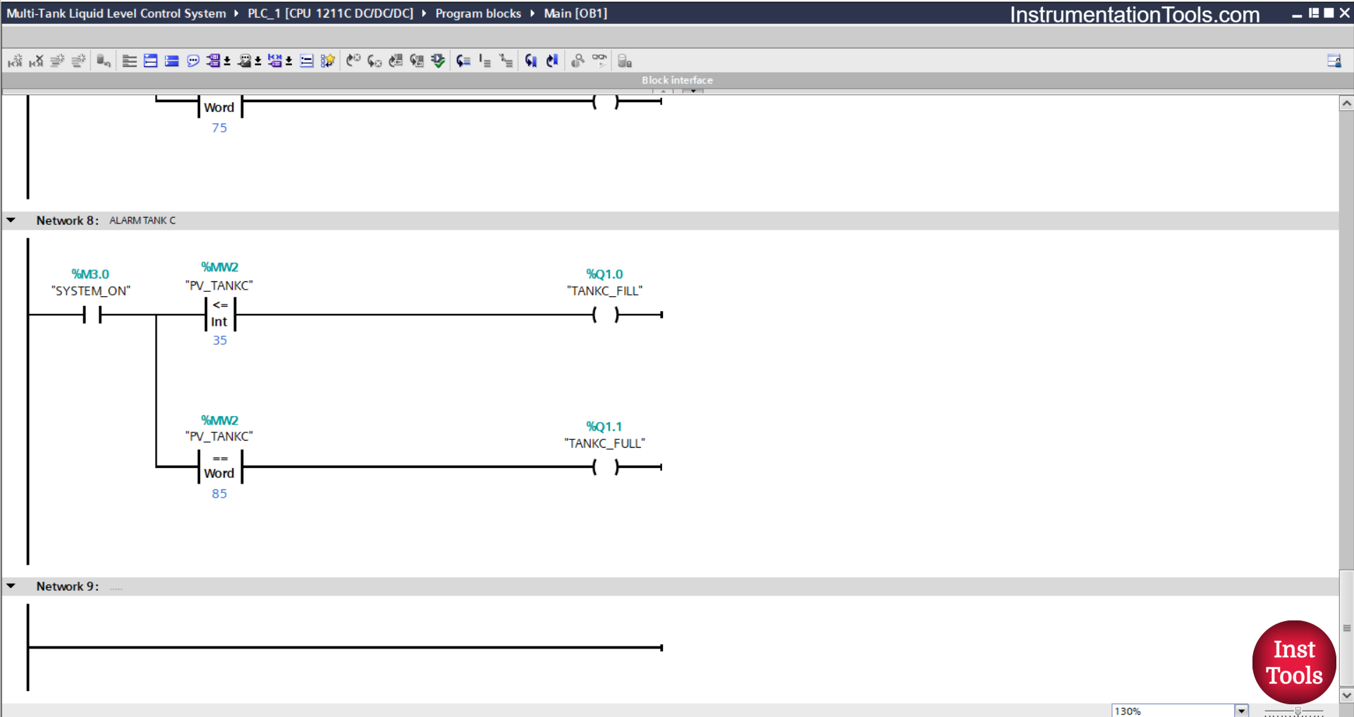
NETWORK 8 (TANK ALARM C)
In this network, when the NO contact of the memory bit SYSTEM_ON (M3.0) is in the HIGH state and the value of the memory word PV_TANKC (MW2) is Less Than Or Equal To “35”, then the TANKC_FILL (Q1.0) output will be ON.
And, if the NO contact of the memory bit SYSTEM_ON (M3.0) in the HIGH state and the value of the memory word PV_TANKC (MW2) is Equal To “85”, then the output TANKC_FULL (Q1.1) will be ON.
Read Next:
- Omron PLC Timers: TIMH, TIMHX, TIMHH, TIMHHX
- Omron PLC BCD Instructions in Ladder Diagram
- Omron PLC Based Vehicle Entry-Exit Tracking System
- Omron Tutorial: Upload and Download PLC Programs
- Omron PLC Tutorial: Binary and BCD Instructions