This article will discuss the implementation of a PLC-based control system using SIMATIC STEP 7 software to automate the process of monitoring and controlling liquid levels in a tank farm. The level sensor is installed on the tank and will send liquid level data to the system. The system will process this data and give commands to the pump to take action to fill the tank. In addition, the system is equipped with an alarm indicator that will activate when the liquid level exceeds the maximum height limit, during the filling process, and when the tank is empty.
Program Objective

System Initialization: The system starts with all components in a ready state, including the level sensor, pump, input valve, output valve (manual), and indicator.
Liquid Level Monitoring: The level sensor continuously monitors the volume of liquid in the tank.
Filling Process:
- Initial Condition: If the liquid level is below the minimum level, the system will start the filling process.
- Input Valve Activation: The input valve will open to allow liquid to flow into the tank.
- Pump Activation: After a 5-second delay, the pump will turn on to pump liquid into the tank.
- Process Termination: When the liquid level reaches the maximum level, the input valve will close and the pump will turn off.
Liquid Emptying: The liquid emptying process is done manually by opening the output valve.
IO Mapping in Siemens STEP 7 PLC
| S.No. | Name Tag | Input (I) | Output (Q) | Memory Bits | Timer |
|---|---|---|---|---|---|
| 1 | START | I0.0 | |||
| 2 | STOP | I0.1 | |||
| 3 | LS_LOW | I0.2 | |||
| 4 | LS_HIGH | I0.3 | |||
| 5 | VALVE_OUT_OPEN | I0.4 | |||
| 6 | VALVE_OUT_CLOSE | I0.5 | |||
| 7 | VALVE_INPUT | Q0.0 | |||
| 8 | PUMP | Q0.1 | |||
| 9 | VALVE_OUT | Q0.2 | |||
| 10 | FILLING_INDICATOR | Q0.3 | |||
| 11 | FULL_INDICATOR | Q0.4 | |||
| 12 | EMPTY_INDICATOR | Q0.5 | |||
| 13 | TIMER1 | DB1 | |||
| 14 | SYSTEM_ON | M0.0 | |||
| 15 | CUTOFF_VALVE_INPUT | M0.1 |
Liquid Level Alarm and Control
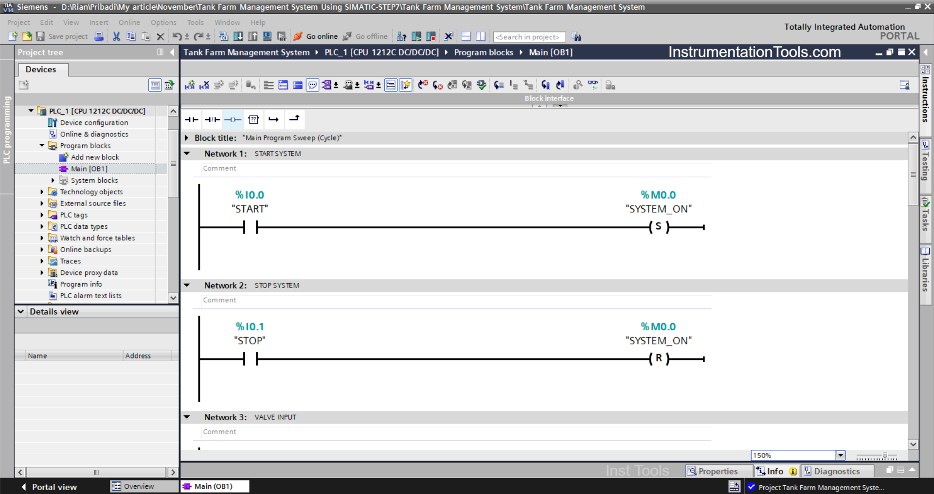
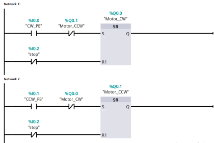
NETWORK 1 (START SYSTEM)
In this Network, the memory bit SYSTEM_ON (M0.0) will be in the HIGH state when the START (I0.0) button is pressed. The memory bit SYSTEM_ON (M0.0) will remain in the HIGH state even though the START (I0.0) button has been released, because it uses the SET OUTPUT instruction.
NETWORK 2 (STOP SYSTEM)
In this Network, if the STOP (I0.1) button is pressed, the memory bit SYSTEM_ON (M0.0) will be in the LOW state. Because it uses the RESET OUTPUT Instruction.
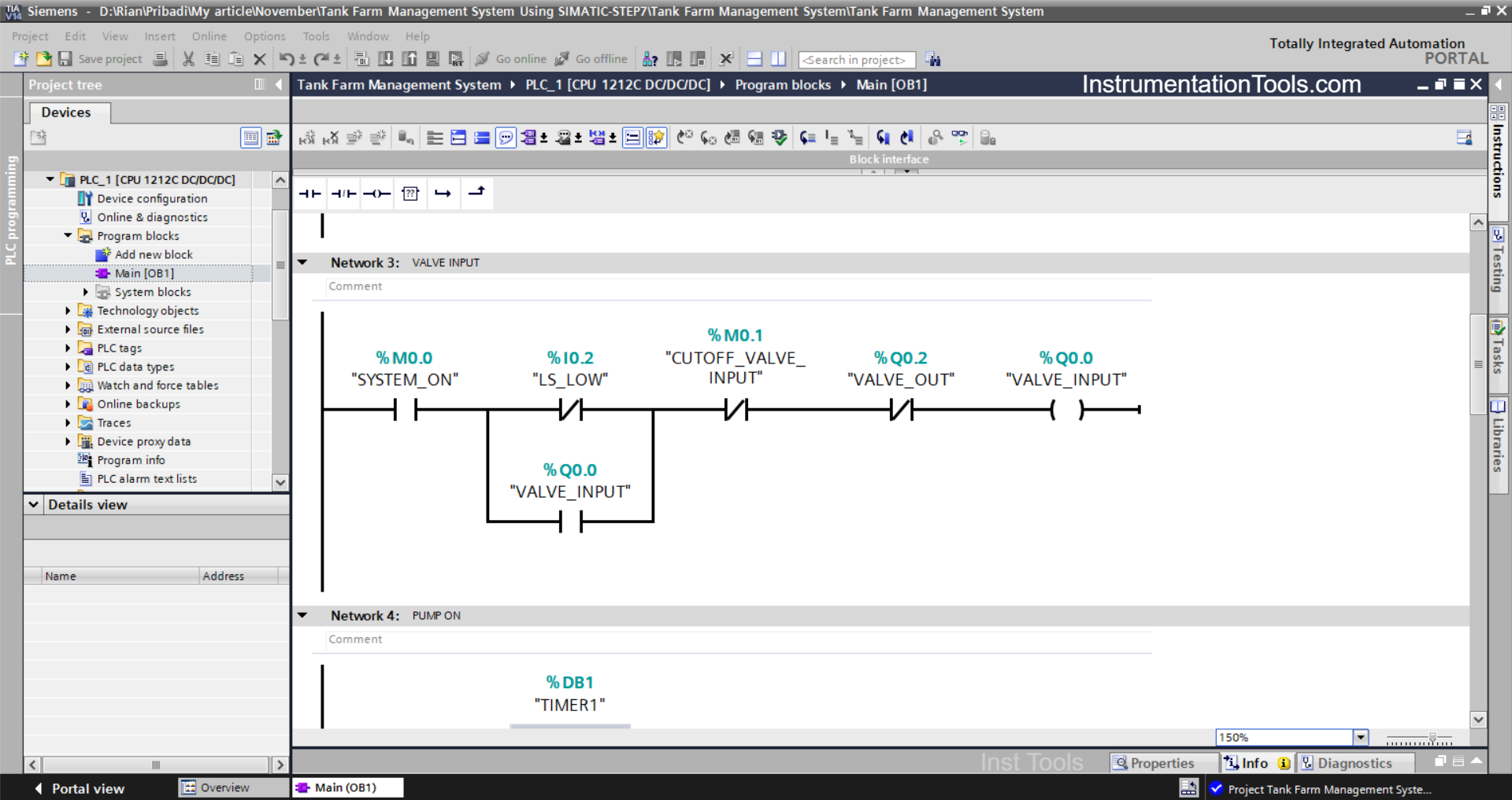
NETWORK 3 (VALVE INPUT)
In this Network, the output VALVE_INPUT (Q0.0) will be OPEN if the NO contact of the memory bit SYSTEM_ON (M0.0) is in the HIGH state and the sensor LS_LOW (I0.2) is in the LOW state.
When the NC contact of CUTOFF_VALVE_INPUT (M0.1) or VALVE_OUT (Q0.2) is in the HIGH state, the output VALVE_INPUT (Q0.0) will be CLOSED.
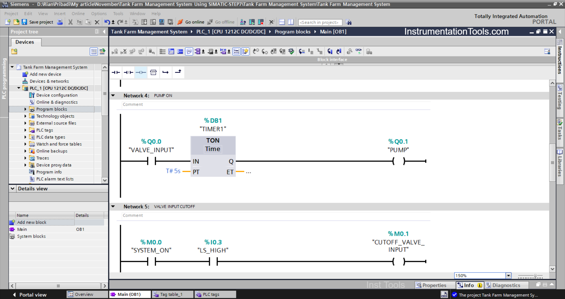
NETWORK 4 (PUMP ON)
In this Network, Timer TIMER1 (DB1) will start counting up to “5” seconds if the NO contact of VALVE_INPUT (Q0.0) is in the HIGH state.
The output PUMP (Q0.1) will be ON when the NO contact of TIMER1(DB1) is in the HIGH state.

NETWORK 5 (VALVE INPUT CUTOFF)
The memory bit CUTOFF_VALVE_INPUT (M0.1) will be in the HIGH state when the NO contacts of the memory bit SYSTEM_ON (M0.0) and Sensor LS_HIGH (I0.3) are in the HIGH state.
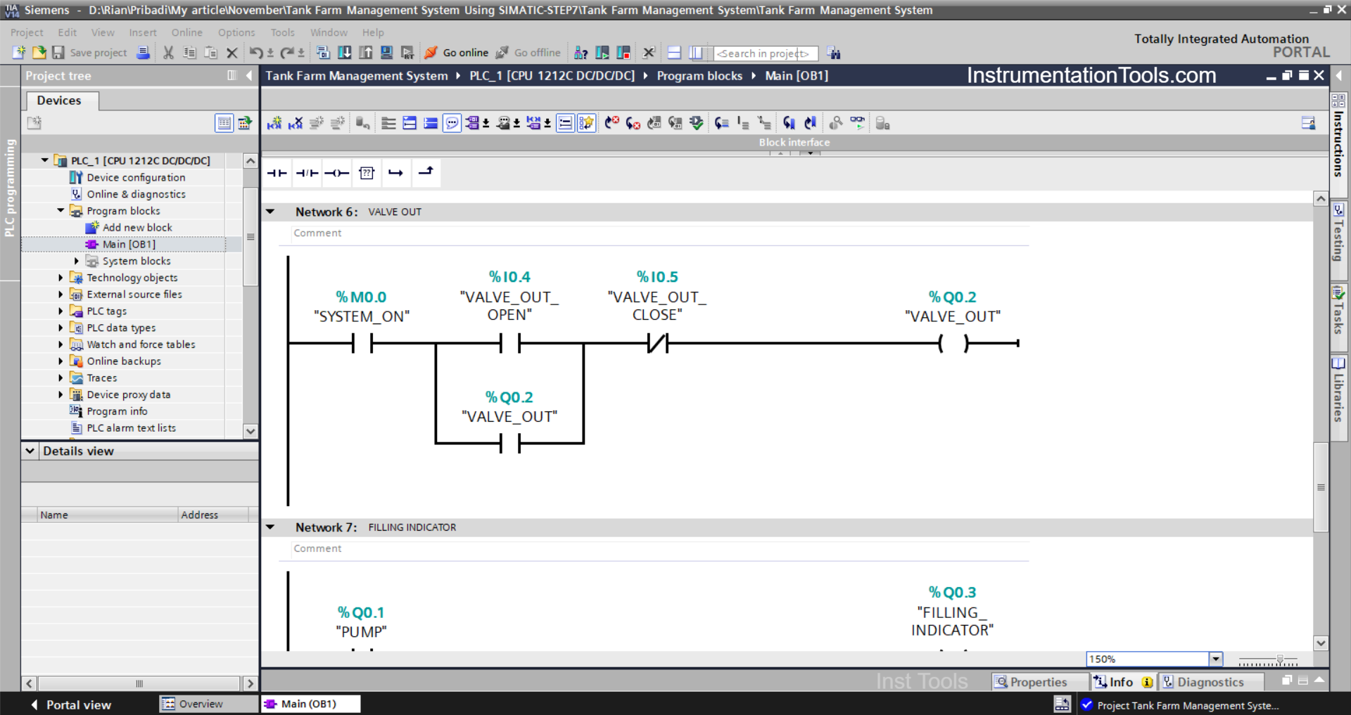
NETWORK 6 (VALVE OUT)
The output VALVE_OUT (Q0.2) will become OPEN when the NO contact of the memory bit SYSTEM_ON (M0.0) in the HIGH state and the VALVE_OUT_OPEN (I0.4) button is pressed.
The output VALVE_OUT (Q0.2) will remain in the OPEN state even though the VALVE_OUT_OPEN (I0.4) button has been released. Because it uses Latching.
And the output VALVE_OUT (Q0.2) will become CLOSE when the VALVE_OUT_CLOSE (I0.5) button is pressed.
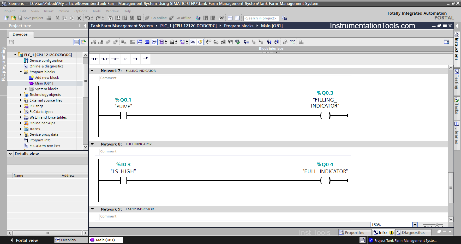
ETWORK 7 (FILLING INDICATOR)
In this Network, the output FILLING_INDICATOR (Q0.3) will be ON when the NO contact of PUMP (Q0.1) is in the HIGH state.
NETWORK 8 (FULL INDICATOR)
In this Network, the output FULL_INDICATOR (Q0.4) will be ON when the NO contact of the sensor LS_HIGH (I0.3) is in the HIGH state.

NETWORK 9 (EMPTY INDICATOR)
In this Network, the output EMPTY_INDICATOR (Q0.5) will be ON when the NC contact of the sensor LS_LOW (I0.2) is in the LOW state.
Read Next:
- SIMATIC PLC Programming for Aquaculture System
- Paint Mixing System Control Program using Siemens PLC
- Vehicle Washing PLC Project: Spray, Brush, Rinse, Dry
- PLC Programming for Fruit Sorting by Weight and Color
- PLC Project for Dam Gate Control with 5 Alarm Levels