Transmitter Output Current Trim (Analog Trim)
It is rare for the analog output current circuitry of a 4-20 mA transmitter to drift. However, should the analog output current be incorrect, use current trim to correct the analog output signal. For instance, if the analog output current is 4.13 mA when it should be 4.00 mA, then current trim is used to adjust it to 4 mA.
Current trim is used to match the transmitter analog output current to the current input of the analog input (AI) card channel on the DCS.
For instance, the transmitter may be reading 0.00% but the DCS may show 0.13% because of differences in current calibration. The DCS may not support current trim of channels in the AI and AO cards. If there is drift in the DCS input circuitry A/D conversion or D/A conversion and output circuitry, current trim has to be done in each device instead.
Current trim is only applicable to transmitter with 4-20 mA analog output. That is, for 4-20 mA/HART transmitters, not for FOUNDATION fieldbus (FF), PROFIBUS-PA, or WirelessHART transmitters, the reason being pure digital transmitters have no 4-20 mA analog output.
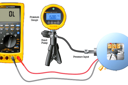
Current trim requires the technician to measure the physical output current from the transmitter. Therefore the technician must either do current trim in the field at the process location by connecting a multimeter to the transmitter test terminals, or the transmitter has to be brought back into the workshop to perform current trim. Current trim in the field is possible using a handheld communicator.
Smart Transmitter Trim Quick Reference
The difference between sensor trim, range setting, and current trim are summarized in the table below:
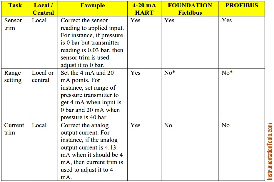
* Range setting in transmitter with digital output only done for DP-flow and DP-level measurement
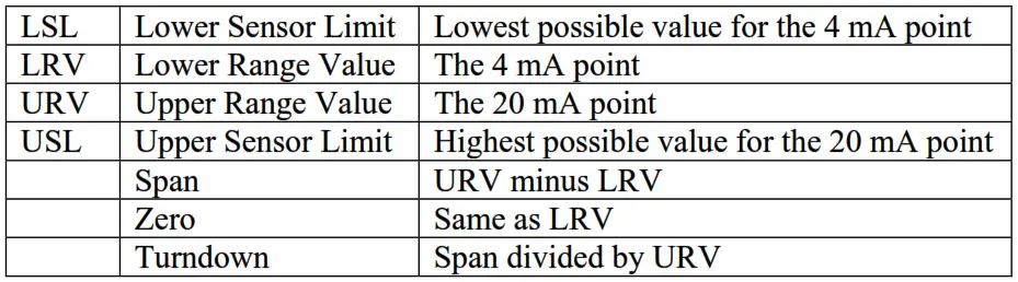
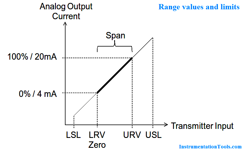
Range Values and Limit Summary
The relationship between range values and limits are summarized in the table below
Valve Positioner Setpoint Current Trim
Similarly, it is rare for the setpoint input current circuitry of a 4-20 mA positioner to drift. However, should the input current sensing be incorrect, use current trim to correct the input signal. For instance, if the current input reads 4.13 mA when it should read 4.00 mA, then current trim is used to adjust it so that the setpoint reads correctly.
Current trim is used to match the positioner current input to the analog output current of the analog output (AO) card channel on the DCS. For instance, the DCS PID output may be 0.00% but the positioner setpoint may show 0.13% because of differences in current calibration.
Current trim is only applicable to positioners with 4-20 mA input. That is, for 4-20 mA/HART positioners, not for FOUNDATION fieldbus (FF) positioners, the reason being pure digital positioners have no 4-20 mA input.
Current trim requires the technician to connect a precision current source or to measure the physical input to the positioner.
Therefore the technician must either do current trim in the field at the valve by connecting a multimeter to the positioner test terminals, or the valve has to be brought back into the workshop to perform current trim. Current trim in the field is possible using a handheld communicator.
Valve Positioner Travel Stroking (Position Feedback Sensor Trim)
Stroking a valve positioner to find its fully opened and fully closed positions is in fact an automated procedure to among other things trim (calibrate) the position transmitter feedback sensor.
That is, it is just like sensor trim for a pressure or temperature transmitter, only that a known reference need not be connected, the positioner will automatically stoke the valve over its full travel to discover the open and closed end-positions.
Likewise, the analog 4-20 mA actual valve position feedback current output of a 4-20 mA positioner is calibrated just like a 4-20 mA transmitter.
Again, this process is not required for FOUNDATION fieldbus positioners or for position feedback transmitters based on WirelessHART.
Sensor Trim Procedure
Plants have a great mix of transmitters for different kinds of measurements from different manufacturers. Since all sensors drift, at some point in time all sensors need a trim. The procedure for calibration depends on the type of transmitter:
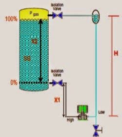
- Pressure transmitter: apply pressure from calibrator or dead weight tester or the manifold can be equalized for zero trim
- Temperature transmitter: apply milli-voltage or resistance from calibrator or resistance decade box
- Flowmeter: has to be calibrated against a prover or master meter
- Valve position transmitter: stroke the valve fully opened and fully closed
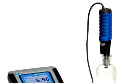
- pH transmitter: put the pH sensor in buffer solutions
The procedure for sensor trim may also vary slightly from one manufacturer to the next depending on the requirement for the particular sensor technology.
Some calibration is easier in the workshop, such as pH sensor buffering where the pH sensor has to be put into with buffer solutions and distilled water. This is easier in the lab.
Smart pH sensors have a memory chip inside making it possible to calibrate the sensor in the lab and bring it to the field, carrying the calibration offset and slope data inside its memory chip. Once connected, the pH transmitter/analyzers upload the calibration data from the sensor memory.
Sensor Zero Trim Calibration
Typical steps in a sensor zero trim calibration for a pressure transmitter are: (Assume HART operating from Remote System)
- Instruct technician to tell operations to put the associated control loop in manual so control is not upset when PV changes when sensor reading changes.
- inform the technician the sensor reading will change.
- Instruct the technician to apply zero physical input (e.g. by isolate, equalize, and vent the manifold).
- Instruct the technician to wait while the sensor reading stabilizes and is corrected by the transmitter.
- Inform the technician the zero sensor trim was successful.
- Instruct technician to tell operations the associated control loop can be put back in automatic.
Article Source : Eddl
Read Next:
Smart Transmitter Tutorial Part 1
Smart Transmitter Tutorial Part 2
Smart Transmitter Tutorial Part 3