This article discusses how to use the Analog Input in the Mitsubishi FX3U Lollette PLC. Analog input in a PLC is a type of input signal that has continuous or varying values, unlike digital signals, which are in the form of ON/OFF states or binary 0/1. There are two types of analog input signals: voltage (with a range of 0–10 V) and current (with a range of 4–20 mA). The PLC converts the incoming analog signal into a 12-bit resolution value (ranging from 0 to 4095). In this program, testing will be conducted using the voltage-type analog input signal (0–10 V) while observing the converted resolution value.
Theoretical Explanation and Program Objective
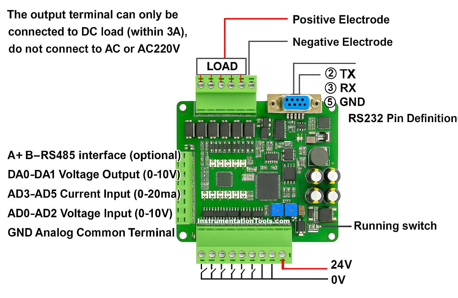
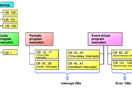
The PLC cannot directly process raw analog voltage/current signals. Therefore, analog inputs must first pass through the PLC’s analog input module, which converts these signals into digital values using ADC (Analog-to-Digital Conversion) and other circuits.
The FX3U PLC features six analog input pins:
- AD0 to AD2 for voltage signals (0-10V)
- AD3 to AD5 for current signals (4-20mA)
In this program, we will utilize Analog Input AD1 for signal processing.
Testing Video
In this video, we tested the PLC hardware with a potentiometer as an analog input.
Analog Input Circuit with Potentiometer
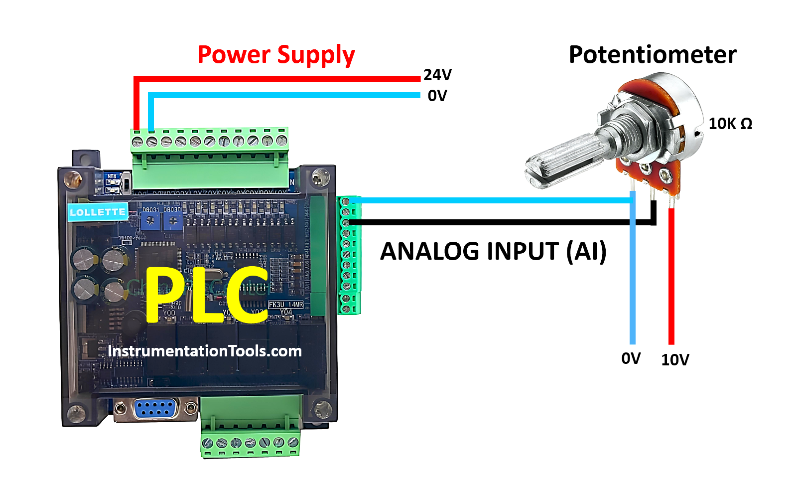
To adjust the voltage value, a 10kΩ potentiometer is required in our testing setup. The potentiometer will be connected to +10V and 0V (GND), while its output terminal will be linked to the Analog Input AD1 of the PLC. Additionally, the PLC requires a 24V DC power supply as its main power source.
Mitsubishi Analog Input Programming
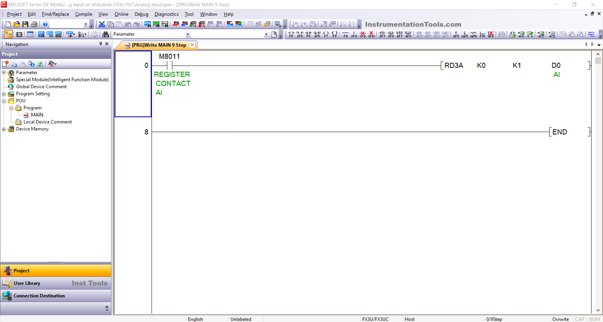
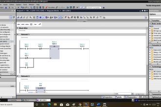
RUNG 0
In this rung, the normally open (NO) contact from REGISTER CONTACT AI (M8011) is a special register address used to activate the RD3A instruction.
The RD3A instruction is used to read the analog input data received.
The value “K0” refers to the module address being used, and “K1” specifies the analog input channel being accessed (AD1).
The memory word AI (D0) is used to store the analog input data received from AD1. The analog input data will be converted into a 12-bit value (ranging from 0 to 4095).
Read Next:
- PLC Program for Sequential Motor Control
- Program for Light Sequences using Timers
- Structured Text Sequential Process Data Storage
- Run 4 Motors Sequentially from 1 Push button
- Mitsubishi PLC Training Course and Tutorials