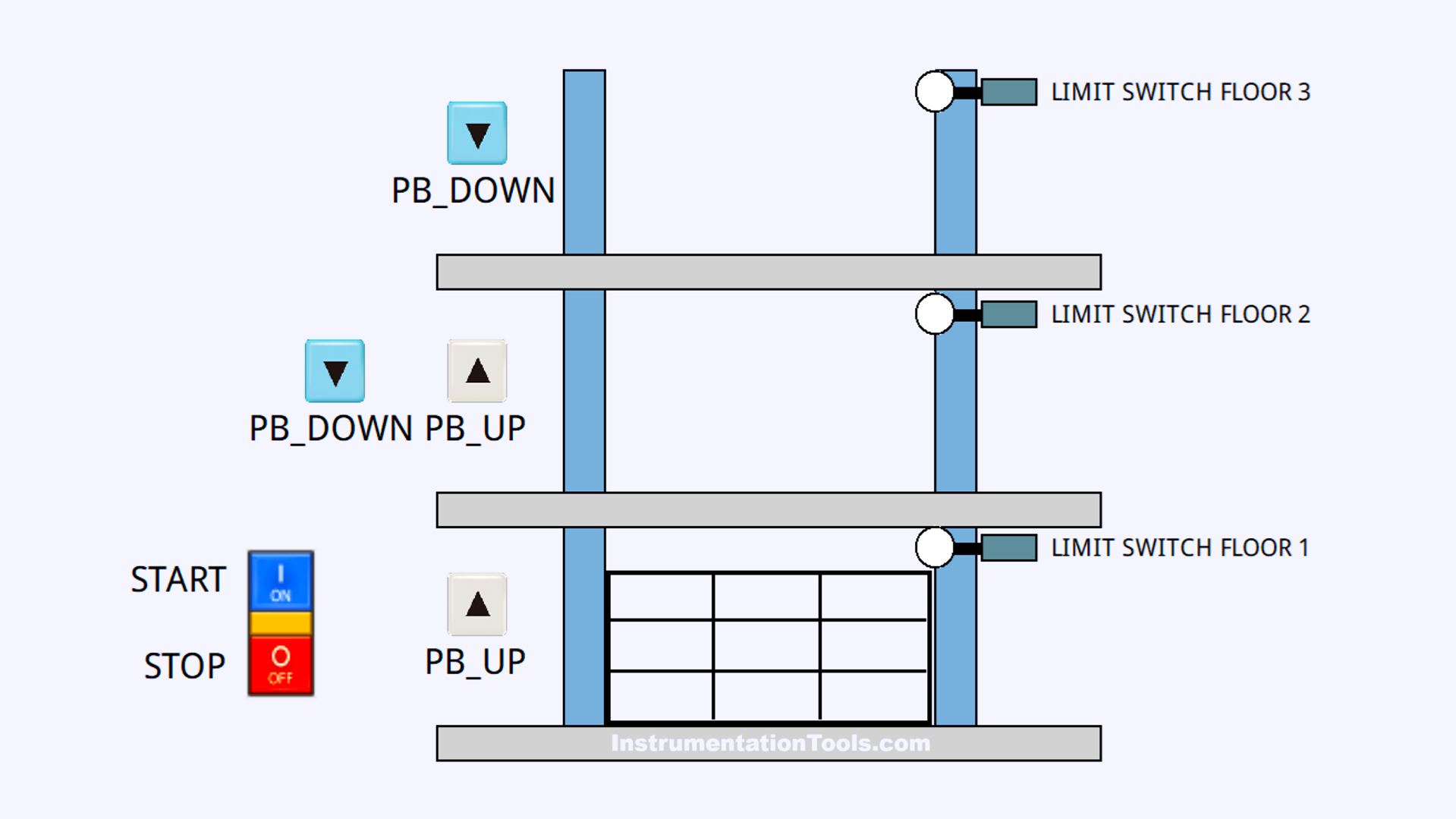
This article discusses the implementation of an automated Cargo Elevator system controlled by Siemens TIA Portal software. This system is only used to operate on 3 floors, with one floor movement. Each floor is equipped with an elevator call button, and a limit switch ensures the elevator stops correctly on each floor. The elevator will only move if the button is pressed and the elevator is on the appropriate floor. When the elevator is on the 1st floor, the elevator can only go up to the 2nd floor. When the elevator is on the 2nd floor, the elevator can go up to the 3rd floor or down to the 2nd floor. And when the elevator is on the 3rd floor, the elevator can only go down to the 2nd Floor.
Program Objective
Elevator Operation Steps:
The elevator can only be run when the system has been started (standby mode).
1st Floor:
- Make sure the elevator is on the 1st floor.
- Only one button is available to go up.
- Press the up button to move the elevator to the 2nd floor automatically.
- The elevator will stop automatically when it reaches the 2nd floor.
2nd Floor:
- The elevator must be on the 2nd floor to operate.
- There are two buttons, namely the up button and the down button.
- Press the up button to move the elevator to the 3rd floor.
- Press the down button to move the elevator back to the 1st floor.
3rd floor:
- The elevator must be on the 3rd floor to operate.
- Only one button is available to go down.
- Press the down button to move the elevator to the 2nd floor.
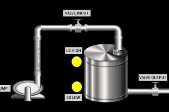
Limit Switches:
Each floor is equipped with a limit switch, which is used to detect the position of the elevator and ensure the elevator stops correctly on the destination floor.
Siemens TIA Portal Project
Inputs and Outputs Details
| S.No. | Comment | Input (I) | Output(Q) | Memory Bit |
| 1 | START | I0.0 | ||
| 2 | STOP | I0.1 | ||
| 3 | LS_FLOOR1 | I0.2 | ||
| 4 | PB_UP_FLOOR2 | I0.7 | ||
| 5 | LS_FLOOR2 | I0.3 | ||
| 6 | PB_UP_FLOOR3 | I1.0 | ||
| 7 | LS_FLOOR3 | I0.4 | ||
| 8 | PB_DOWN_FLOOR1 | I0.5 | ||
| 9 | PB_DOWN_FLOOR2 | I0.6 | ||
| 10 | FLOOR1_TO_2 | Q0.0 | ||
| 11 | FLOOR2_TO_3 | Q0.2 | ||
| 12 | FLOOR2_TO_1 | Q0.1 | ||
| 13 | FLOOR3_TO_2 | Q0.3 | ||
| 14 | SYSTEM_ON | M0.0 | ||
| 15 | IR_LS_FLOOR1 | M0.1 | ||
| 16 | IR_LS_FLOOR2 | M0.2 | ||
| 17 | IR_LS_FLOOR3 | M0.3 |
Cargo Elevator for 3 Floors
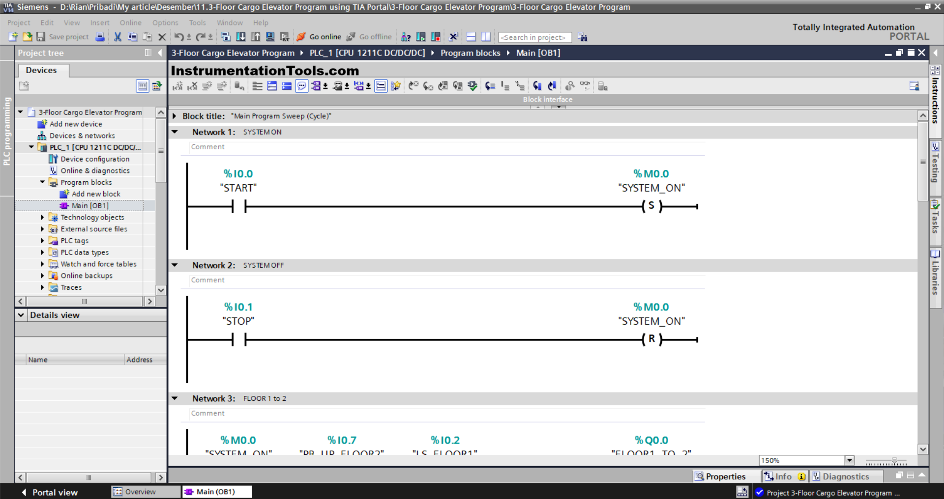
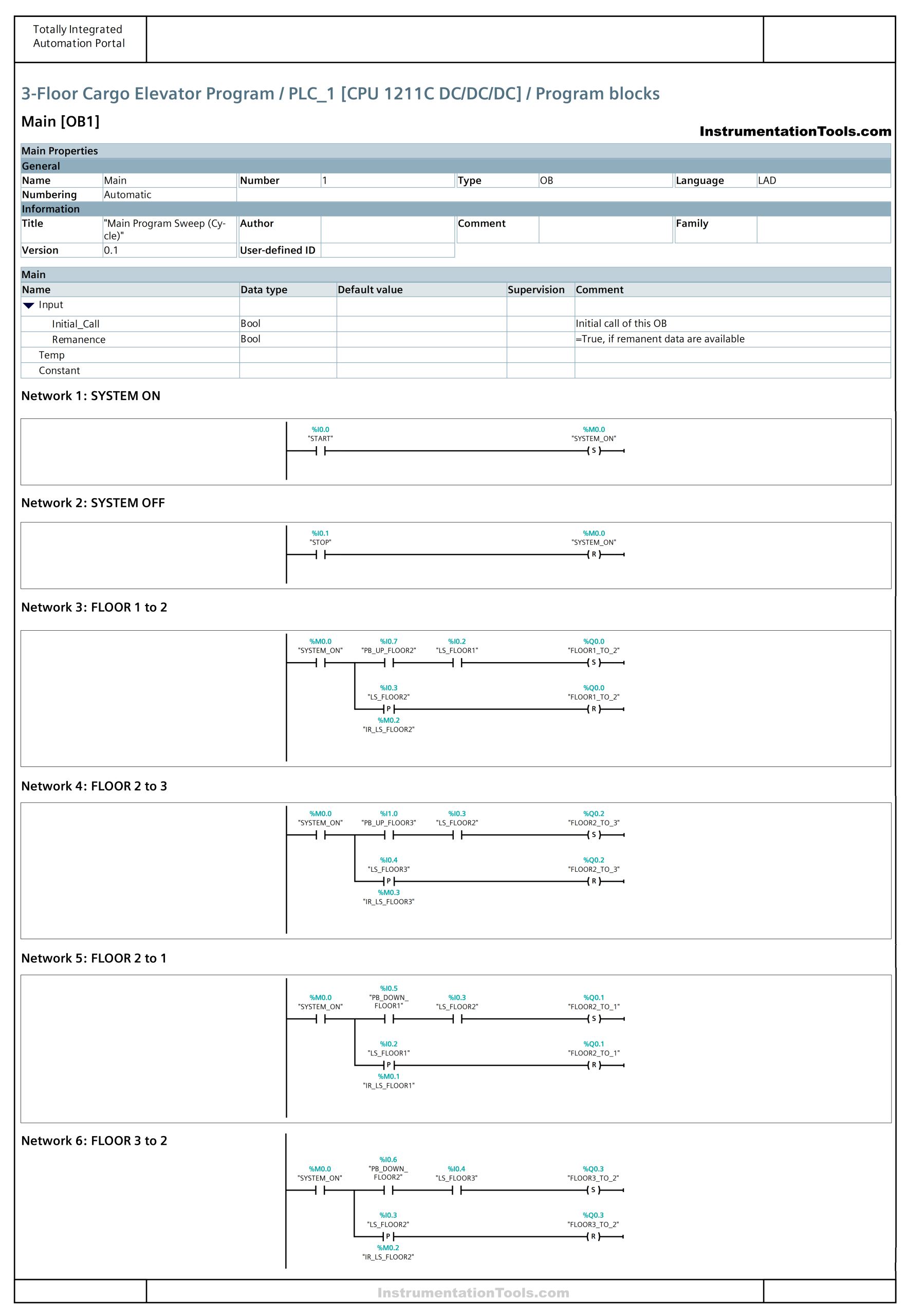
NETWORK 1 (START SYSTEM)
In this network, when the START (I0.0) button is Pressed, the memory bit SYSTEM_ON (M0.0) will be in the HIGH state. Because it uses Instruction Set output, even though the START (I0.0) button has been Released the memory bit SYSTEM_ON (M0.0) will remain in the HIGH state.
NETWORK 2 (STOP SYSTEM)
In this network, when the STOP (I0.1) button is Pressed, the memory bit SYSTEM_ON (M0.0) will be in the LOW state. Because it uses the Reset output instruction, even though the START (I0.0) button has been Released the memory bit SYSTEM_ON (M0.0) will remain in the LOW state.
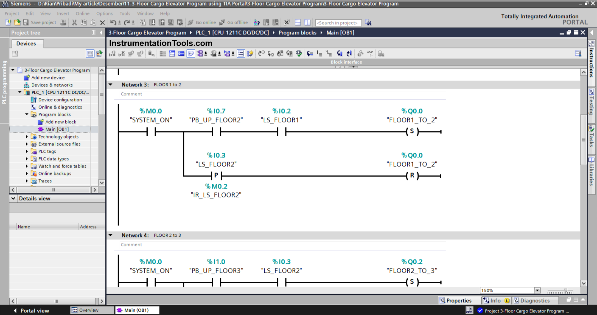
NETWORK 3 (FLOOR 1 to 2)
In this network, the output FLOOR1_TO_2 (Q0.0) will be ON when the NO contact of the memory bit SYSTEM_ON (M0.0) and the limit switch LS_FLOOR1 (I0.2) are in the HIGH state, and the PB_UP_FLOOR2 (I0.7) button is Pressed.
Even though the PB_UP_FLOOR2 (I0.7) button has been Released and the limit switch LS_FLOOR1 (I0.2) is in the LOW state, the FLOOR1_TO_2 (Q0.0) output will remain in the ON state. Because it uses Instruction Set output.
Because it uses the Reset output instruction, the output FLOOR1_TO_2 (Q0.0) will be OFF when the Limit switch LS_FLOOR2 (I0.3) is in the HIGH state.
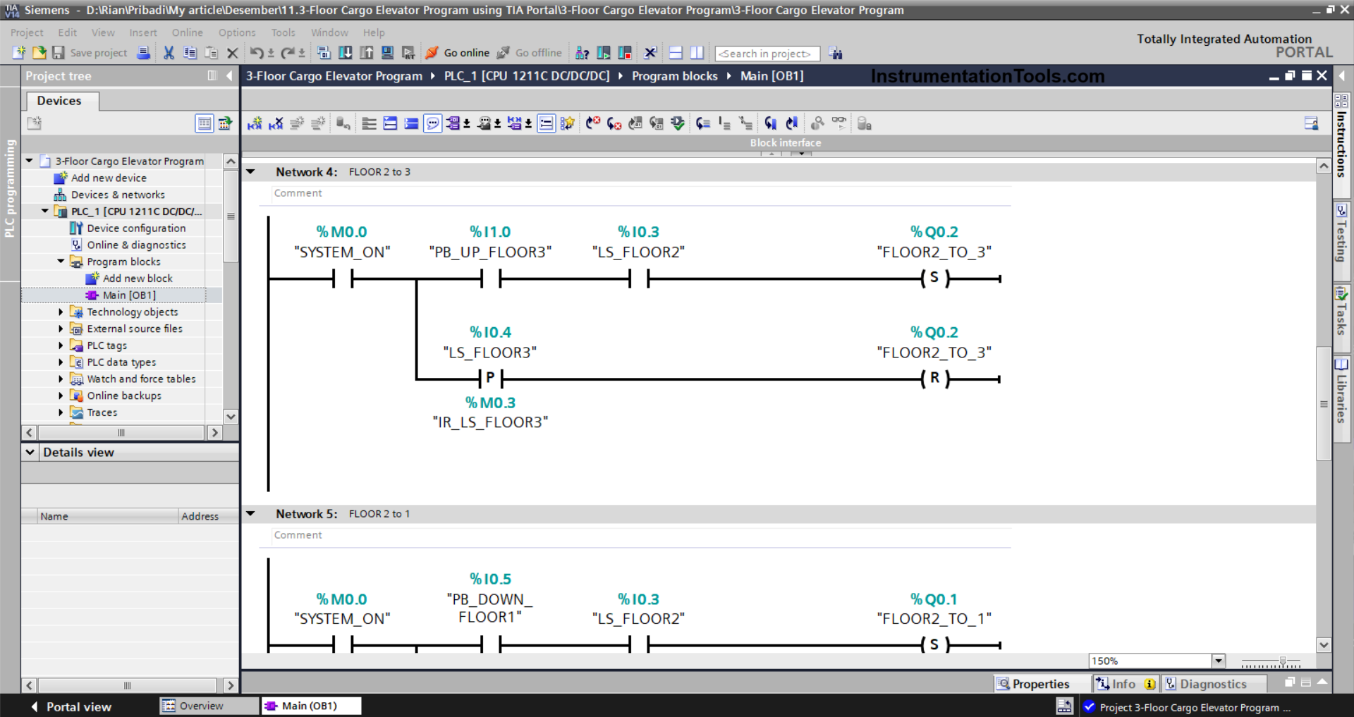
NETWORK 4 (FLOOR 2 to 3)
In this network, the output FLOOR2_TO_3 (Q0.2) will be ON when the NO contact of the memory bit SYSTEM_ON (M0.0) and the limit switch LS_FLOOR2 (I0.3) are in the HIGH state, and the PB_UP_FLOOR3 (I1.0) button is pressed.
Even though the PB_UP_FLOOR3 (I1.0) button has been Released and the limit switch LS_FLOOR2(I0.3) is in the LOW state, the FLOOR2_TO_3 (Q0.2) output state will remain in the ON state. Because it uses Instruction Set output.
Because it uses the Reset output instruction, when the limit switch LS_FLOOR3 (I0.4) is in the HIGH state, the output FLOOR2_TO_3 (Q0.2) will be OFF.
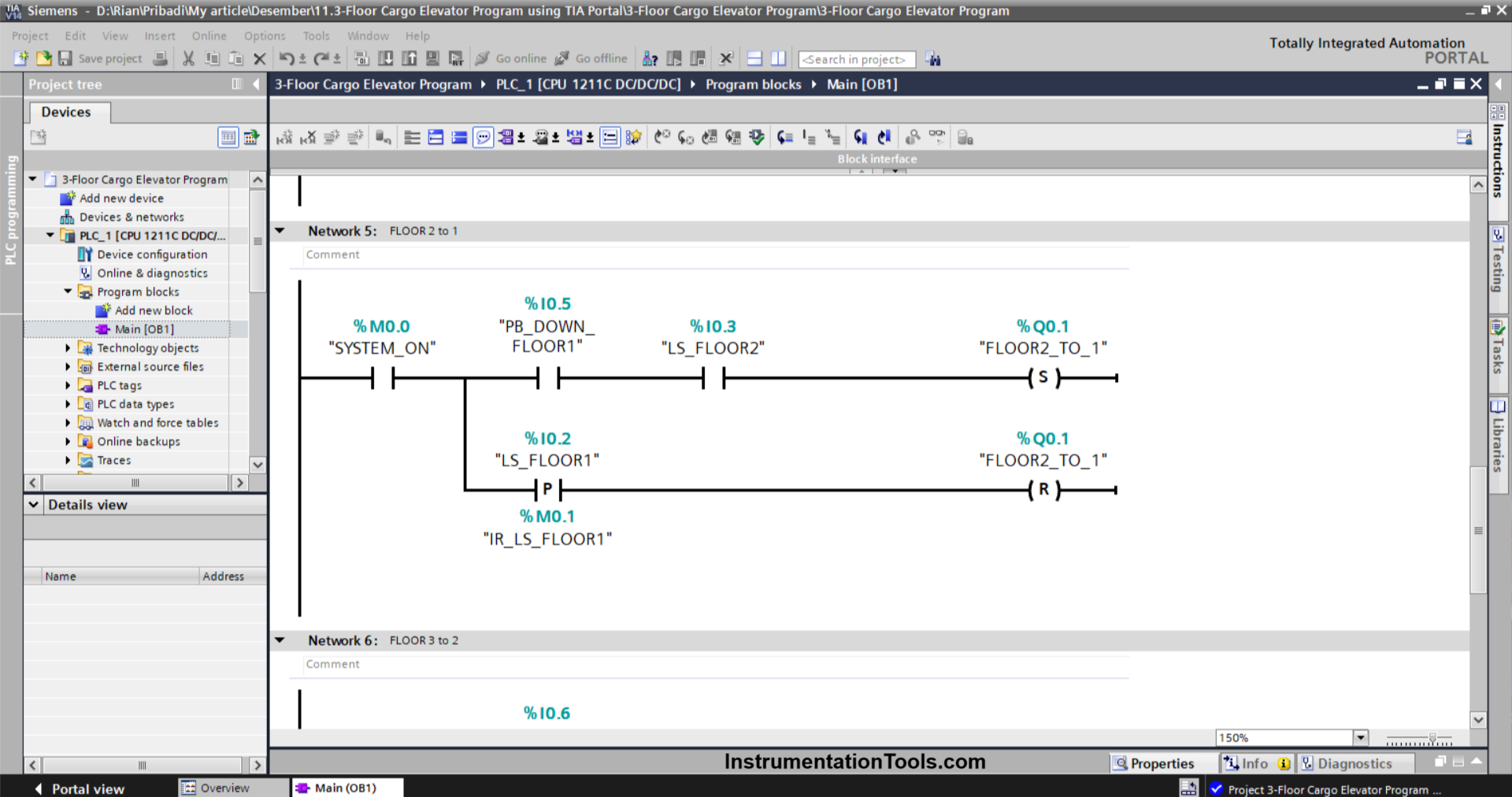
NETWORK 5 (FLOOR 2 to 1)
In this Network, the output FLOOR2_TO_1 (Q0.1) will be ON when the NO contact of the memory bit SYSTEM_ON (M0.0) and the limit switch LS_FLOOR2 (I0.3) are in the HIGH state, and the PB_DOWN_FLOOR1 (I0.5) button is Pressed.
Even though the PB_DOWN_FLOOR1 (I0.5) button has been Released and the limit switch LS_FLOOR2 (I0.3) in the LOW state, the output state of FLOOR2_TO_1 (Q0.1) will remain in the ON state. Because it uses Instruction Set output.
Because it uses the Reset output instruction, when the Limit switch LS_FLOOR1 (I0.2) is in the HIGH state, the output FLOOR2_TO_1 (Q0.1) will be OFF.
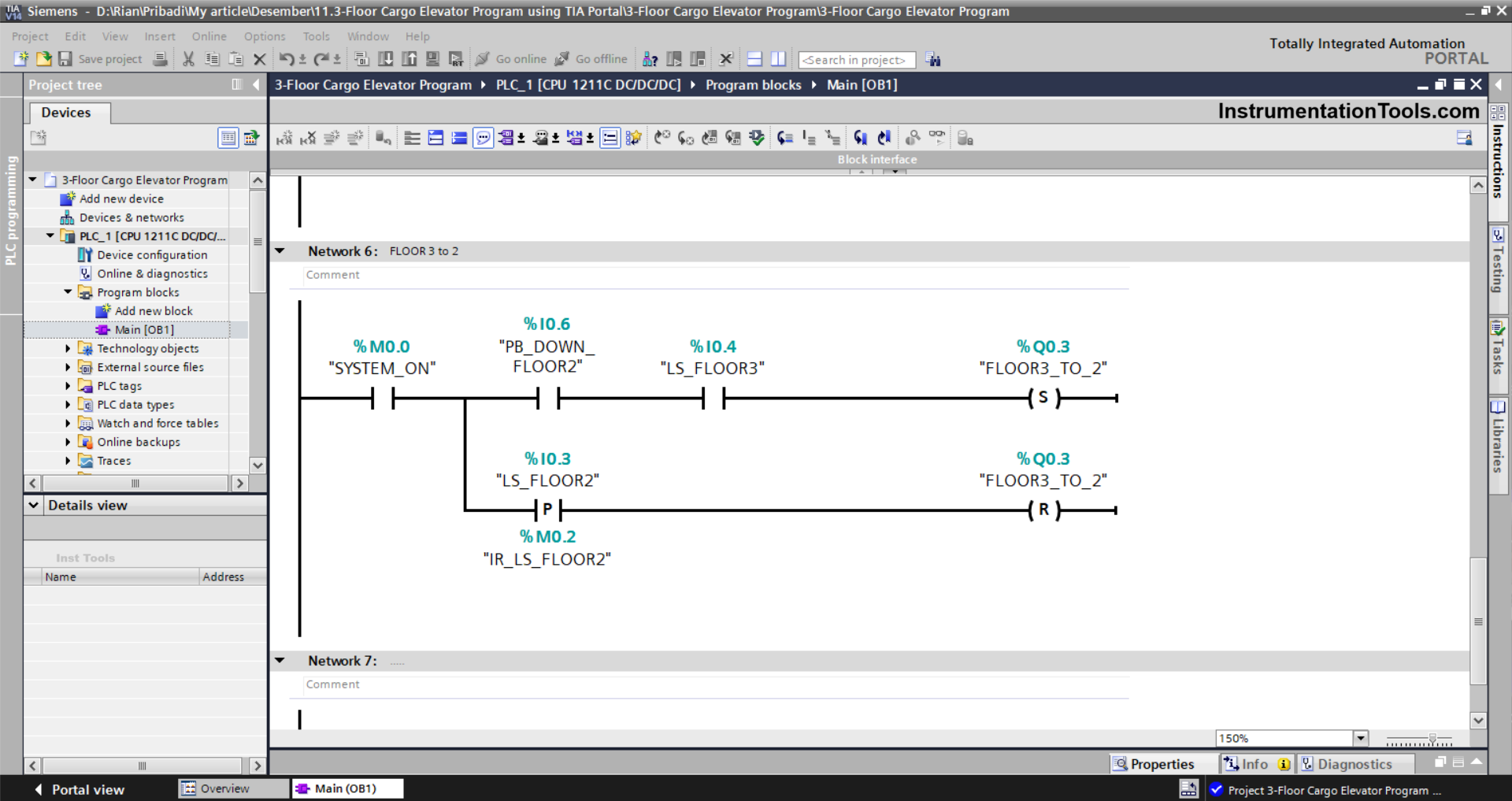
NETWORK 6 (FLOOR 3 to 2)
In this Network, the output FLOOR3_TO_2 (Q0.3) will be ON when the NO contact of the memory bit SYSTEM_ON (M0.0) and the limit switch LS_FLOOR3 (I0.4) are in the HIGH state, and the PB_DOWN_FLOOR2 (I0.6) button is Pressed.
Even though the PB_DOWN_FLOOR2 (I0.6) button has been Released and the limit switch LS_FLOOR3 (I0.4) is in the LOW state, the output state of FLOOR3_TO_2 (Q0.3) will remain in the ON state. Because it uses Instruction Set output,
Because it uses the Reset output instruction, when the limit switch LS_FLOOR2 (I0.3) is in the HIGH state, the output FLOOR3_TO_2 (Q0.3) will be OFF.
Read Next:
- PLC Emergency Stop Example Program
- Ladder Logic Example with Timers
- Motor Control Start & Stop Timer Circuit
- PLC Programming Example on Timers
- Converter Instruction in Siemens PLC


