HART, an acronym for Highway Addressable Remote Transducer, is an open process control network protocol and was introduced in the late 1980s. It is a hybrid communication protocol that uses the Bell 202 Frequency Shift Keying (FSK) technique to superimpose digital communication signal on top of the analog 4–20 mA current loop signal. It is supported by the HART Communication Foundation (HCF). Unlike the other “open” digital communication technologies applied to process instrumentation, HART is compatible with existing systems.
For many years, the process automation and control industry is dominated by 4–20 mA analog signal to carry process variable (PV) and control signals to and from the control room. The HART protocol extends this analog communication with additional bidirectional digital communication, being carried by the same wiring at the same time. This digital signal, known as HART signal, carries device configuration, diagnostic information, calibration, and any additional process measurements.
Some of the features of the HART protocol are as follows:
- Simultaneous analog and digital communication
- Compatible with conventional analog instrumentation schemes
- Supports multivariable field devices
- Flexible data access via up to two masters
- Open de facto standard
- Backward compatible
- Only protocol that supports both analog and digital, unlike other fieldbuses that are digital in nature
- Either point-to-point or multidrop operation
- Adequate response time of ~0.5 s
EVOLUTION AND ADAPTATION OF HART PROTOCOL
HART was introduced by Rosemount in the 1980s. Initially, the idea was to support the 4–20 mA loop current with digital PV signals. The diagnostic, calibration, troubleshooting capabilities, etc., of HART led to its increasing acceptance. This was even more so since the existing cables were utilized to carry the HART signals. The field personnel working at the sites did not have to learn much, and a small handheld master was all that was needed for in situ calibration, etc., of the instruments. With little training, the field personnel were able to adapt themselves with the working of HART signals. This led to the wide acceptance of HART technology. Fierce competition from other competing technologies led to its further development. Revision 4 was the first version that was introduced in the market having HART compatibility. Later, revision 5 was introduced in 1989 by Rosemount, which has a huge installed base. It supports the latter version of the HART protocol.
HART is the only protocol that supports both analog and digital (hybrid) communication at the same time over the same pair of wires. Because of its widespread acceptability, the HART User Group was formed in 1990 and HCF was formed in 1993. With the formation of HCF, Rosemount transferred ownership of all patents, trademarks, and technology to the Foundation.
HART AND SMART DEVICES
Developments in the fields of smart field devices and HART technology went on at around the same time. As more and more functionalities started emerging from the smart or intelligent field devices, more demands were placed from HART technology to complement them. This led to further developments in either of them. Smart instruments are connected to programmable logic controllers (PLCs), computers, etc., which collect sensor, actuator, or field instrument data and diagnostics by digital communication techniques.
Most smart instruments have the following capabilities: zero, span, and range adjustments; diagnostics to verify health; and memory to store status and configuration information. They support two-way communications with the controller, digitize the process signal, and digitally correct PVs. They contain advanced software that performs measurements, and control actions are taken accordingly. Smart instruments add more resolution, more accuracy, and above all more reliability to the process. At the site, various diagnostics can be verified in a few minutes by the handheld controller associated with HART technology.
Initially, HART was developed with the primary PV in mind. Later, PVs included upper and lower transducer limits, etc. Status information was later included to lend more and more functionalities.
Smart field devices of today are almost always multivariable in nature and supported by HART technology. For example, a flow meter includes a totalizer and a data logger. Initially, system manufacturers were slow to exploit the full capabilities associated with HART, but with time came the realizations and today, the huge installed base of HART-compatible multivariable field devices are fully utilized to support them.
HART ENCODING AND WAVEFORM
The HART protocol makes use of the FSK technique to superpose the digital communication on top of 4–20 mA signals. The digital FSK signal is phase continuous and has a 0.5 mA amplitude having two different frequencies, 1200 Hz and 2200 Hz, representing binary 1 and 0, respectively. Since the average DC value of a sine wave over a time period is zero, the FSK signal does not add any DC component on the 4–20 mA analog signal.
The below Figure shows the digital HART signal superimposed on the 4–20 mA analog signal. The HART field devices and the central controller have FSK modems— the FSK-modulated HART signals are carried along with the 4–20 mA analog signal via the same wires. At the controller, the HART signal is demodulated and actions taken accordingly.
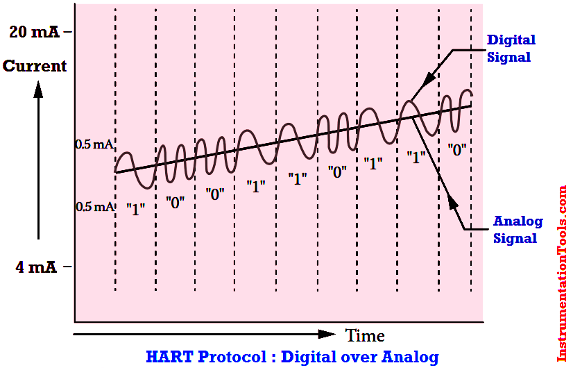
Fig : HART digital signal superimposed on 4–20 mA analog signal.
HART CHARACTER
HART uses an asynchronous mode for communication purpose. Thus, HART data are transmitted 1 byte at a time without any clock signal. A HART character is composed of 11 bits and shown in Below Figure.
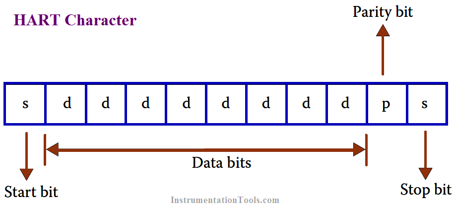
The character starts with a start bit, followed by eight bits of data, one parity bit, and lastly one stop bit. The parity bit provides integrity to the data transmitted.


Every topics discussed here is very informative and useful for our interviews. thank you very much.
very good
Thank you Sir.
Most of these topics were not covered at College.
Your explanation is so simple and understandable.
Very effective
where can I download the library in C, I need to parse the hart protocol for the slave device