Micro-electronics is advancing day by day to new heights. Because embedded systems and VLSI are required in any system due to the chip requirements in each and every electronic device, new and efficient technologies must always be adapted to cater to ever-increasing demands.
Nevertheless, one of the recent technologies which is most used for its reliability and efficiency is SMD or surface mount device. In this post, we will see how to use SMD components.
What is an SMD component?
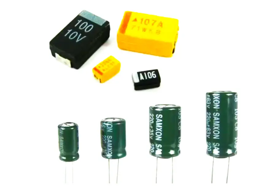
Refer to the below image. The left-hand side shows normal capacitors and the right-hand side shows SMD capacitors. We can understand this simply by seeing the image.
SMD stands for surface mount device. As the name implies, electronic components like resistors, capacitors, inductors, transistors, and other semiconductors are mounted directly on the surface of the chip; eliminating the need to solder the long leads of normal semiconductors.
Due to this, the space consumed is much less by an SMD component. The leads will consume space in the chip for them to be soldered, which will thus require the distance between two holes to be large. But in SMD, the distance between two holes is very small as the component itself has small leads inside it to be directly mounted as plug and play.
The SMD leads will then be soldered on the chip and it will look like it is directly mounted on the surface (as can be understood through the image); whereas in normal ones, you can clearly see the leads coming outside. (Normal semiconductor mounting is also called through-hole technology.)
Due to less amount of space consumed in a space, you can place many components on a chip. The density is thus increased, allowing for more complex functionaries to work. Also, they can be placed on both sides of the chip due to surface mounting technology. SMD components are mostly soldered automatically through automated machines, which allows mass production to increase swiftly.
There are various SMD components like resistors, capacitors, inductors, diodes, transistors, transformers, fuses, crystal oscillators, and ICs. They come in various shapes and codes. Each code is necessary to be understood so that the correct ones are picked and placed.
Selection Factors
So, when you are choosing the correct SMD component for your application, you need to consider the following factors –
- the physical dimension of the component as well as PCB,
- check compatibility with other components,
- check voltage,
- current and efficiency
- check bandwidth and frequency.
So, overall physical and electrical characteristics are considered for choosing the right SMD component for your application.
Difference between SMD and Through-Hole
- SMD consumes very little space in a chip, thus allowing more density on the board. This is not possible in through-hole technique components.
- Solder joints are much more proper in SMD components because you get a good amount of area for soldering. If the area is less, then soldering too will become complex.
- SMD is more prone to electromagnetic noise and other interference due to good frequency characteristics.
- Mass production is much easier and faster for SMD components than through-hole components.
- SMD components are costlier than through-hole components.
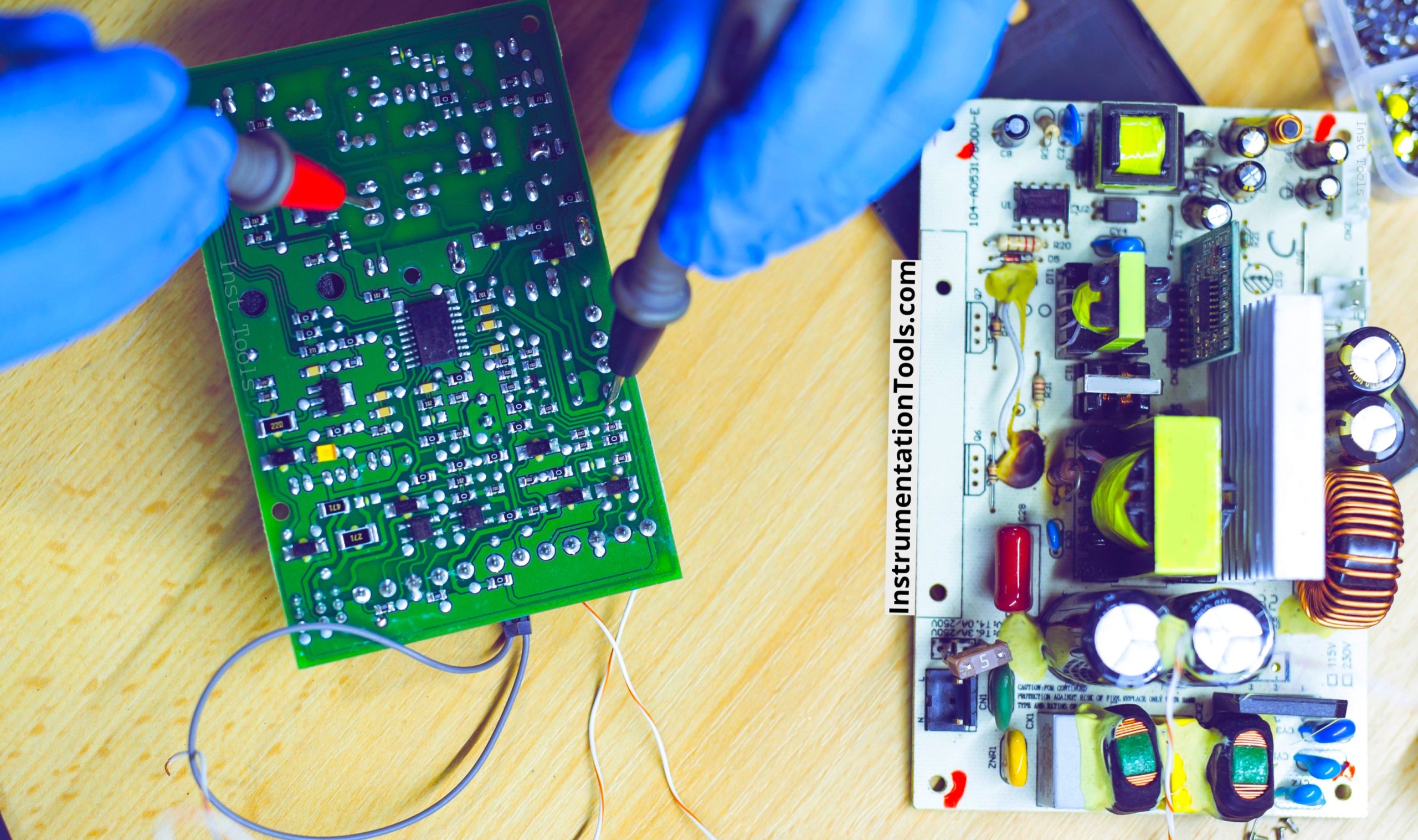
How to Solder SMD Components?
SMD components can be soldered and desoldered either manually by a solder gun or through automatic machines where it is baked like it is in an oven. As of now, we will look into manual operation.
If you are soldering manually, then you need the following tools like – solder wire, a soldering gun with a small tip or corresponding tip size, a pair of tweezers (used for pulling or grasping), PCB with available pads and markings, SMD component, flux cleaner, anti-static cloth, and a small metal pick.
Firstly, ensure that your board is ready with holes and conductor lines. Once done, you need to identify the corresponding component location where your SMD device will be placed.
After that, clean the surface with a good abrasive sponge to remove any oxidation on it. Now, heat the solder gun and keep the solder metal wire ready along with you. Once heated, first pre-tin the area where soldering will be done. This aids the bonding process more smoothly.
After that, pick the component and solder it in that area. Remember not to over-solder, otherwise, it will spread in unwanted areas and cause a short-circuit. Now, clean the surface which has been soldered. When you are soldering capacitors, remember to understand it’s forward biasing or reverse biasing is working, and mount them accordingly. Also, use tweezers to hold the component properly and solder it in the place you require.
In this way, we saw how to use SMD components in electronic circuits.