By using this site, you agree to the Privacy Policy and Terms of Use.
Accept
Inst ToolsInst ToolsInst Tools
  • Courses
  • PLC Tutorials
  • Control Systems
Search
All rights reserved. Reproduction in whole or in part without written permission is prohibited.
Reading: Structured Text PLC Code for Sequential Process Data Storage
Share
Notification Show More
Font ResizerAa
Inst ToolsInst Tools
Font ResizerAa
  • Courses
  • PLC Tutorials
  • Control Systems
Search
  • Ask
  • Courses
  • Videos
  • Q & A
    • Interview
    • MCQ
  • EE
    • Electronics
    • Electrical
  • Measure
    • Control Valves
    • Calibration
    • Temperature
    • Pressure
    • Flow
    • Level
    • Analyzers
    • Switches
    • Vibration
    • Solenoid Valve
  • Control
    • PLC Tutorials
    • Control Systems
    • Safety Instrumented System (SIS)
    • Communication
    • Fire & Gas System
  • More
    • Design
    • Tools
    • Animation
    • Basics
    • Formulas
    • Standards
    • TextBooks
    • Common
    • Software
    • Excel Tools
    • Erection & Commissioning
    • Process Fundamentals
    • Videos
    • Books
Follow US
All rights reserved. Reproduction in whole or in part without written permission is prohibited.
Inst Tools > Blog > PLC Tutorials > Structured Text PLC Code for Sequential Process Data Storage

Structured Text PLC Code for Sequential Process Data Storage

Learn how to write a structured text PLC code to store data from sequential processes using the case statement.

Last updated: September 18, 2024 2:34 pm
Viral Nagda
PLC Tutorials
No Comments
Share
3 Min Read
SHARE

In this post, we will write a PLC code to store data of various processes sequentially. We will use structured text language for this.

Contents
Sequential Process Data StorageStructured Text PLC Code

Sequential Process Data Storage

Let us understand the case scenario first. There are two sensors in the system – temperature and pressure. And in total, there are five processes. Process start and stop are not in our control, we will just get the status of the process (whether it is running or stopped).

When the five processes start in sequence, we get a complete signal from each process when over. With this signal, we must store the current value of temperature and pressure in different registers. The values of these registers will be updated after the corresponding process is over every time.

Following are the PLC IO’s:

  1. Digital inputs – Process complete signal
  2. Analog inputs – Temperature transmitter, pressure transmitter.

Structured Text PLC Code

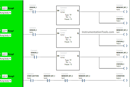
Let us see the logic now. Refer to the below image. It is a very simple logic where we use a case statement. We first use a sequence counter to see in which the current step is running.

We increment the counter on every input signal of the process completely received. The set value of the counter will be five, as per the five processes running.

We will reset the counter when the counter is done.

Structured Text PLC Program for Sequential Process Data Storage

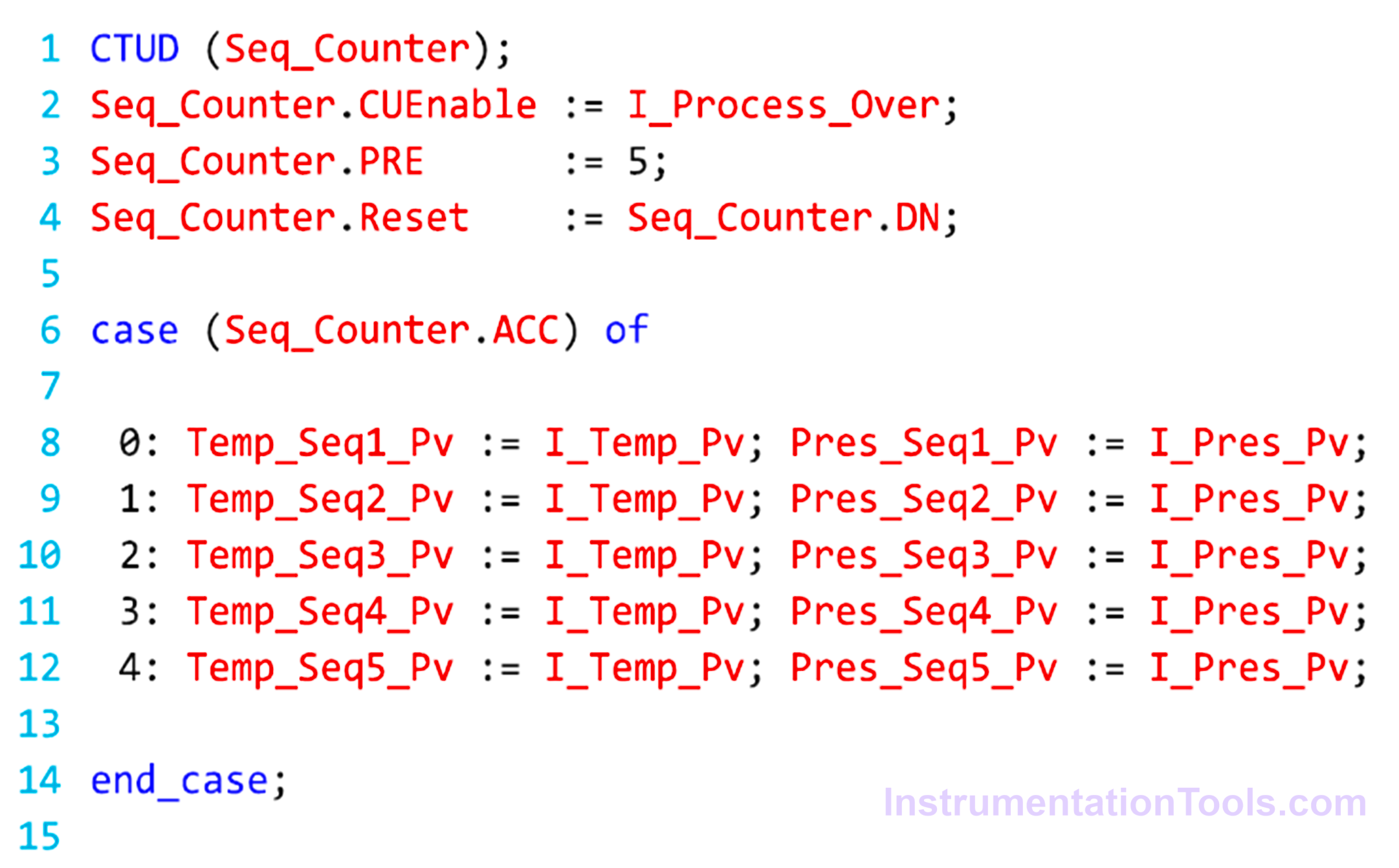
In the next step, we use a case statement. We use five cases. As the counter increments on receiving the process complete signal, this means the current counter value is the current step running. So, we use the case number from 0 to 4, where 0 means step 1 and 4 means step-5.

In each case, we use two different registers of temperature storage and pressure storage. For incrementing the case, we use the counter current value as a case reference. This will ensure that in each step, only the corresponding registers will be written.

In this way, we saw how to write a PLC program to store data of various processes sequentially.

Read Next:

  • PLC Program for Sequential Motor Control
  • Run Motors Sequentially using PLC Program
  • Sequential PLC Program Pneumatic Valve
  • PLC Program for Water Level Control Logic
  • Compare Combinational & Sequential Circuit
Don't Miss Our Updates
Be the first to get exclusive content straight to your email.
We promise not to spam you. You can unsubscribe at any time.
Invalid email address
You've successfully subscribed !
PLC Memory Mapping and I/O addressing
PID Block in RSLogix 500
Structured Text PLC Programming for Two-Tanks Level Application
Ladder Logic Programming Examples
How to Use Diagnostic Buffer for SIEMENS PLC?
Share This Article
Facebook Whatsapp Whatsapp LinkedIn Copy Link
Share
Leave a Comment

Leave a Reply Cancel reply

Your email address will not be published. Required fields are marked *

Stay Connected

128.3kFollowersLike
69.1kFollowersFollow
208kSubscribersSubscribe
38kFollowersFollow

Categories

Recent Comments

  • MIHARITSOA Aina Sitraka on Top Non-PLC Certification Courses for Automation Professionals
  • Vaishnavi on Free Instrumentation Course for Trainee Engineers
  • anuj kapoor on DCS Program to Maintain Draft in Furnace
  • anuj kapoor on IoT based Smart Boiler Control System with Cloud PLC and SCADA

Related Articles

Hardwired IO and Serial IO - Differences Explained

Hardwired I/O and Serial I/O – Differences Explained

Water Fountain Control Logic

Water Fountain Control Logic – PLC Exercises and Solutions

Simatic S7 PLC Backup Steps

How to take Backup from Siemens S7-300 PLC?

Function of Racks in PLC System

Function of Racks in PLC – Types of SIEMENS S7-400 PLC Racks

Example Program Logic in Allen Bradley PLC

PLC Programming Examples on Industrial Automation

sinking-and-sourcing-digital-output-modules

PLC Digital Signals Wiring Techniques

How-to do Security of SCADA Systems

How-to do Security of SCADA Systems?

PLC Software Redundancy

Software Redundancy in Siemens PLC – Hardware versus Software

More Articles

Machine Learning

Difference Between Machine Learning and Artificial Intelligence?

Siemens TIA Portal program blocks

Tia Portal – Optimized and Standard Data Block Access

Power Electronics Objective Questions

Advanced Three Phase Converter Objective Questions

UX Design

How to Achieve Sustainability in UX Design and Make a Difference?

P&ID Guidelines for Pumps Heat Exchangers

P&ID Guidelines for Pumps Heat Exchangers

Inductive Transducers Objective Questions

Inductive Transducers Objective Questions

How a PLC communicates with Transmitters

How PLC Reads the Data from Field Transmitters

types-of-total-organic-carbon

Basics of Total Organic Carbon (TOC) Analyzers

Follow US
All rights reserved. Reproduction in whole or in part without written permission is prohibited.
Welcome Back!

Sign in to your account

Username or Email Address
Password

Lost your password?