An illustration sometimes find helpful in understanding analog signal ranges is to consider the signal range as a length expressed on a number line.
4-20mA Graphical Calculations
For example, the common 4-20 mA analog current signal range would appear as such:

If one were to ask the percentage corresponding to a 14.4 mA signal on a 4-20 mA range, it would be as simple as determining the length of a line segment stretching from the 4 mA mark to the 14.4 mA mark:

As a percentage, this thick line is 10.4 mA long (the distance between 14.4 mA and 4 mA) over a total (possible) length of 16 mA (the total span between 20 mA and 4 mA). Thus:

Percentage = 65%
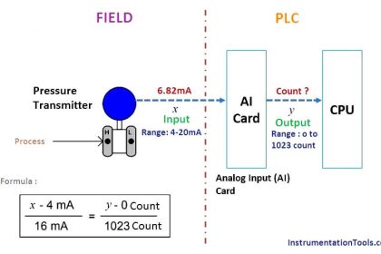
This same “number line” approach may be used to visualize any conversion from one analog scale to another. Consider the case of an electronic pressure transmitter calibrated to a pressure range of −5 to +25 PSI, having an (obsolete) current signal output range of 10 to 50 mA.
The appropriate current signal value for an applied pressure of +12 PSI would be represented on the number line as such:

Finding the “length” of this line segment in units of milliamps is as simple as setting up a proportion between the length of the line in units of PSI over the total (span) in PSI, to the length of the line in units of mA over the total (span) in mA:
Solving for the unknown (?) current by cross-multiplication and division yields a value of 22.67 mA.
Of course, this value of 22.67 mA only tells us the length of the line segment on the number line; it does not directly tell us the current signal value.
To find that, we must add the “live zero” offset of 10 mA, for a final result of 32.67 mA.

Thus, an applied pressure of +12 PSI to this transmitter should result in a 32.67 mA output signal.
Read Next:
- History of 3-15 psi & 4-20 mA
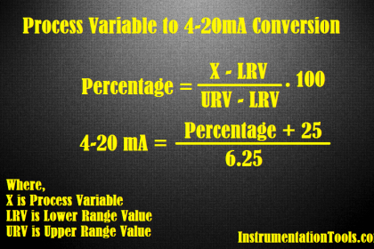
- 4-20mA Conversions Easily
- Zero and Span Calibration
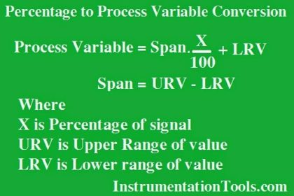
- Process Variable Conversion
- Calculate Temperature Transmitter


Thanks for the info.
very nice useful for all our inst dept shadnagar hyd
l like this courso for me can you send this courso for my email