Inst ToolsInst ToolsInst Tools
  • Courses
  • Automation
    • PLC
    • Control System
    • Safety System
    • Communication
    • Fire & Gas System
  • Instrumentation
    • Design
    • Pressure
    • Temperature
    • Flow
    • Level
    • Vibration
    • Analyzer
    • Control Valve
    • Switch
    • Calibration
    • Erection & Commissioning
  • Interview
    • Instrumentation
    • Electrical
    • Electronics
    • Practical
  • Q&A
    • Instrumentation
    • Control System
    • Electrical
    • Electronics
    • Analog Electronics
    • Digital Electronics
    • Power Electronics
    • Microprocessor
  • Request
Search
  • Books
  • Software
  • Projects
  • Process
  • Tools
  • Basics
  • Formula
  • Power Plant
  • Root Cause Analysis
  • Electrical Basics
  • Animation
  • Standards
  • 4-20 mA Course
  • Siemens PLC Course
Reading: DP Level Measurement Problems
Share
Notification Show More
Font ResizerAa
Inst ToolsInst Tools
Font ResizerAa
  • Courses
  • Design
  • PLC
  • Interview
  • Control System
Search
  • Courses
  • Automation
    • PLC
    • Control System
    • Safety System
    • Communication
    • Fire & Gas System
  • Instrumentation
    • Design
    • Pressure
    • Temperature
    • Flow
    • Level
    • Vibration
    • Analyzer
    • Control Valve
    • Switch
    • Calibration
    • Erection & Commissioning
  • Interview
    • Instrumentation
    • Electrical
    • Electronics
    • Practical
  • Q&A
    • Instrumentation
    • Control System
    • Electrical
    • Electronics
    • Analog Electronics
    • Digital Electronics
    • Power Electronics
    • Microprocessor
  • Request
Follow US
All rights reserved. Reproduction in whole or in part without written permission is prohibited.
Inst Tools > Blog > Erection & Commissioning > DP Level Measurement Problems

DP Level Measurement Problems

Last updated: June 5, 2019 5:25 pm
Editorial Staff
Erection & Commissioning Level Measurement
2 Comments
Share
3 Min Read
SHARE

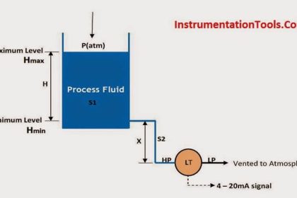
The DP level measurement techniques use inferred (indirect method) processes and not direct measurements. Namely, the indication of fluid level is based on the pressure exerted on a differential pressure (DP) cell by the height of the liquid in the vessel. This places great importance on the physical and environmental problems that can affect the accuracy of this indirect measurement.

Connections

As amusing as it may sound, many avoidable errors occur because the DP cell had the sensing line connections reversed.

In systems that have high operating pressure but low hydrostatic pressure due to weight of the fluid, this is easy to occur. This is particularly important for closed tank systems.

With an incorrectly connected DP cell the indicated level would go down while the true tank level increases.

Over-Pressuring

Three valve manifolds are provided on DP cells to prevent over-pressuring and aid in the removal of cells for maintenance. Incorrect procedures can
inadvertently over-pressure the differential pressure cell. If the cell does not fail immediately the internal diaphragm may become distorted. The measurements could read either high or low depending on the mode of failure.

Note that if the equalizing valve on the three-valve manifold is inadvertently opened, the level indication will of course drop to a very low level as the pressure across the DP cell equalizes.

Sensing lines

The sensing lines are the umbilical cord to the DP cell and must be functioning correctly.

Some of the errors that can occur are:

1. Obstructed sensing lines

The small diameter lines can become clogged with particulate, with resulting inaccurate readings. Sometimes the problem is first noted as an unusually sluggish response to a predicted change in level. Periodic draining and flushing of sensing lines is a must.

2.Draining sensing lines

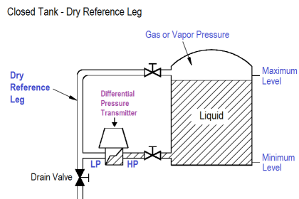
As mentioned previously, the lines must be drained to remove any debris or particulate that may settle to the bottom of the tank and in the line. Also, in closed tank dry leg systems, condensate must be removed regularly to prevent fluid pressure building up on the low-pressure impulse line.

Failure to do so will of course give a low tank level reading. Procedural care must be exercised to ensure the DP cell is not over-ranged inadvertently during draining. Such could happen if the block valves are not closed and equalizing valve opened beforehand.

False high level indication can be caused by a leaking or drained wet leg. A leaking variable (process) leg can cause false low-level indication.

Don't Miss Our Updates
Be the first to get exclusive content straight to your email.
We promise not to spam you. You can unsubscribe at any time.
Invalid email address
You've successfully subscribed !

Continue Reading

Installation & Commissioning Tips for HART Devices
Hydrostatic Interface Level Measurement
Interface Level Measurement using DP Transmitter
Zero Elevation and Zero Suppression in Level Measurement
Basics of DP Transmitter Suppression and Elevation
Capacitive Level Switch Principle
Share This Article
Facebook Whatsapp Whatsapp LinkedIn Copy Link
Share
2 Comments
  • Abdullah says:
    November 5, 2016 at 8:37 am

    Sir please make app for apple

    Reply
  • godfather says:
    December 22, 2017 at 4:37 pm

    it is there mr abdullah

    Reply

Leave a Reply Cancel reply

Your email address will not be published. Required fields are marked *

Stay Connected

128.3kFollowersLike
69.1kFollowersFollow
210kSubscribersSubscribe
38kFollowersFollow

Categories

Explore More

Ultrasonic Level Switch Working Principle
Radiation Level Measurement
Turbine Flow Meter Installation Procedure
Radar Tank Gauging
Basics of Sight Glass Level Gauge
Comparison of Level Meters – Level Measurement Instruments
Tube Fitting Types
Bubbler Level Measurement Animation

Keep Learning

Contact-Type-GWR-Level-Transmitter-Working-Animation

Probe Type GWR Level Transmitter Working Animation

Pipeline Project Management

Pipeline Project Management

Level Sensor Pressure vessel mounting

Level Instruments Design Rules

Wet Leg Level Transmitter

Basics of DP Level Measurement

Ultrasonic level measurement

Ultrasonic Level Measurement

Displacement Level Transmitter in situ calibration

Displacer (buoyancy) Level Transmitter Principle, Limitations, Design, Installation & Calibration

Rotary Level Switch Working Principle Animation

Rotary Level Switch Working principle Animation

Ultrasonic Level Measurement Questions and Answers

Ultrasonic Level Measurement Questions and Answers

Learn More

Transformer voltage and turns ratio

Transformer Voltage Ratio

Instrumentation Inspection and Quality Control Questions

Instrumentation Inspection and Quality Control Questions

Boolean Logic to PLC Programming

Boolean Logic to PLC Programming

Flexible Input Output Modules

Flexible Input Output Modules

Steam Turbine Interlocks

What are the Interlocks for Steam Turbine?

Vortex Flow Meters

All About Vortex Flow Meters

Satellites Application in Agriculture

The Most Significant Developments in Satellite Technology

Vortex Flow Meter Animation

Basic Working Principle of Vortex Flowmeter

Menu

  • About
  • Privacy Policy
  • Copyright

Quick Links

  • Learn PLC
  • Helping Hand
  • Part Time Job

YouTube Subscribe

Follow US
All rights reserved. Reproduction in whole or in part without written permission is prohibited.
Welcome Back!

Sign in to your account

Username or Email Address
Password

Lost your password?