Inst ToolsInst ToolsInst Tools
  • Courses
  • Automation
    • PLC
    • Control System
    • Safety System
    • Communication
    • Fire & Gas System
  • Instrumentation
    • Design
    • Pressure
    • Temperature
    • Flow
    • Level
    • Vibration
    • Analyzer
    • Control Valve
    • Switch
    • Calibration
    • Erection & Commissioning
  • Interview
    • Instrumentation
    • Electrical
    • Electronics
    • Practical
  • Q&A
    • Instrumentation
    • Control System
    • Electrical
    • Electronics
    • Analog Electronics
    • Digital Electronics
    • Power Electronics
    • Microprocessor
  • Request
Search
  • Books
  • Software
  • Projects
  • Process
  • Tools
  • Basics
  • Formula
  • Power Plant
  • Root Cause Analysis
  • Electrical Basics
  • Animation
  • Standards
  • 4-20 mA Course
  • Siemens PLC Course
Reading: PLC Program for Boolean Expression
Share
Font ResizerAa
Inst ToolsInst Tools
Font ResizerAa
  • Courses
  • Design
  • PLC
  • Interview
  • Control System
Search
  • Courses
  • Automation
    • PLC
    • Control System
    • Safety System
    • Communication
    • Fire & Gas System
  • Instrumentation
    • Design
    • Pressure
    • Temperature
    • Flow
    • Level
    • Vibration
    • Analyzer
    • Control Valve
    • Switch
    • Calibration
    • Erection & Commissioning
  • Interview
    • Instrumentation
    • Electrical
    • Electronics
    • Practical
  • Q&A
    • Instrumentation
    • Control System
    • Electrical
    • Electronics
    • Analog Electronics
    • Digital Electronics
    • Power Electronics
    • Microprocessor
  • Request
Follow US
All rights reserved. Reproduction in whole or in part without written permission is prohibited.
Inst Tools > Blog > PLC Tutorials > PLC Program for Boolean Expression

PLC Program for Boolean Expression

In this article, you will learn the PLC program for Boolean expression and learn the plc automation with basic logic.

Last updated: March 25, 2024 2:35 pm
Editorial Staff
PLC Tutorials
No Comments
Share
4 Min Read
SHARE

In this article, you will learn the PLC program for Boolean expression and learn the plc automation with basic logic.

Contents
PLC ProgramBoolean to PLC ConversionInputsOutputsBoolean Expression Ladder LogicLogic DescriptionTest Results

Please note: The logic diagram example provided here is designed for educational use for students and engineers to learn PLC fundamentals.

PLC Program

Problem Statement

Design a PLC ladder logic for the following Boolean Expression.

We are using toggle Inputs to control the output.

Convert the given boolean logic to PLC ladder logic.

Y = A(BC+D)

Boolean to PLC Conversion

Watch the below PLC tutorial video to learn the basics.

PLC Logic - Boolean Expression Based Example

Inputs

Digital Inputs:

The list of inputs are listed.

A: I0.0

B: I0.1

C: I0.2

D: I0.3

Outputs

Digital Outputs:

The list of outputs are listed.

Y: Q0.0

Boolean Expression Ladder Logic
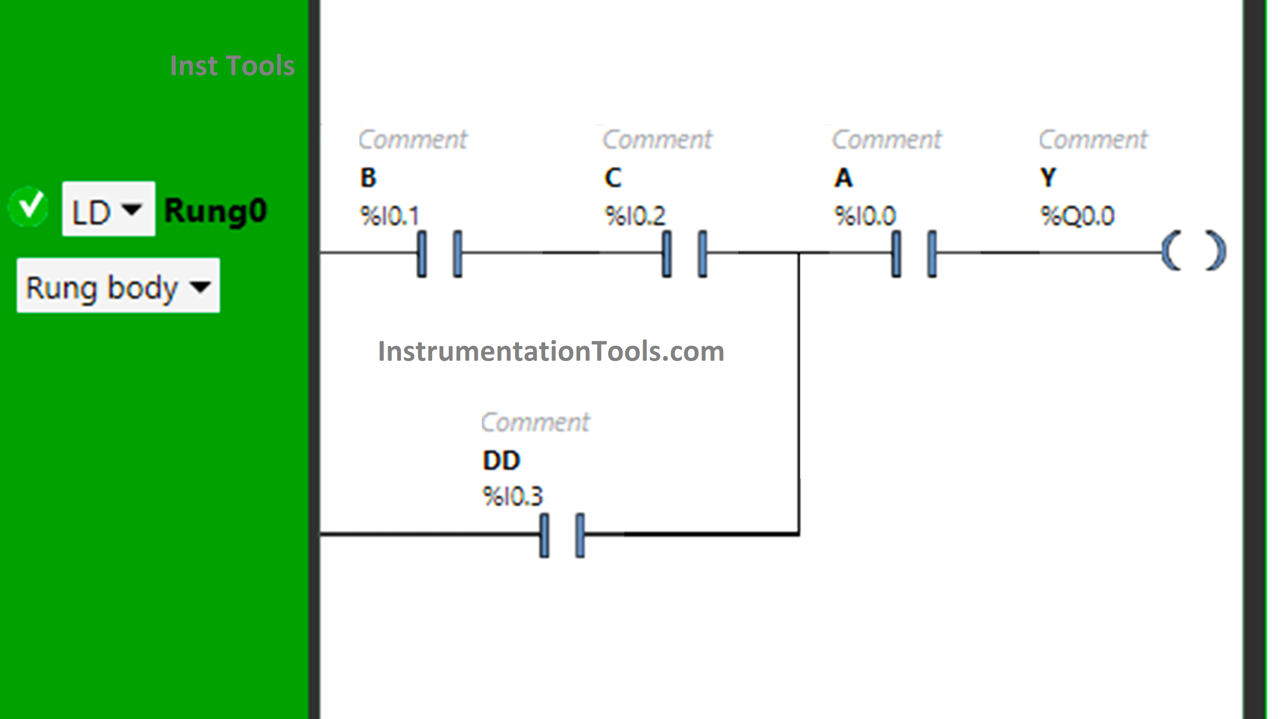
PLC Program for Boolean Expression

Logic Description

  • We used the EcoStruxure Machine Expert Basic software for PLC programming.
  • In the above program, Normally Open Contacts are used for inputs A, B, C, and D.
  • Input B and Input C are connected in series, thus implementing AND Logic Gate.
  • The Input D is connected in parallel with the output of BC, thus implementing OR Logic Gate.
  • Then there is again the implementation of AND Logic Gate as the Input A is connected in series with the output of BC+D.
  • For output Y (Q0.0) to be ON, either Input B, Input C, and Input A should be ON, or Input D and Input A should be ON.
  • Turning OFF Input A will turn OFF  Y (Q0.0), even if all remaining Inputs are turned ON.

Test Results

Now we simulate the program with different input statuses.

When Input B, Input C, and Input A are ON
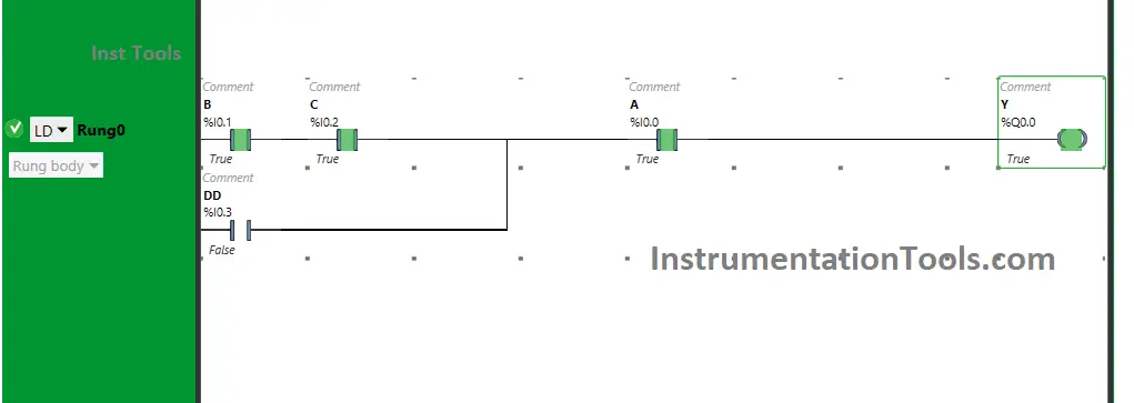
Boolean Expression Ladder Logic

When  Input B, Input C and Input A are turned ON, the output Y (Q0.0) will turn ON. If one of  these Inputs are turned OFF, Y(Q0.0) is turned OFF. These inputs are used as Normally Open Contacts and are connected in series.

Therefore, all the inputs should be ON so that the output Y (Q0.0) will turn ON. The output Y (Q0.0) will not turn ON, if all the inputs i.e., B, C and D are not turned ON.

When both Input D and Input A are ON
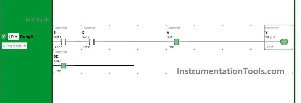
PLC Boolean Conversion

Y (Q0.0) will turn ON When Input D and Input A are turned ON. As the input D is connected in parallel with the output of BC, instead of turning ON the inputs B and C, the input D will also allow the signal to pass when turned ON.

The inputs D and A are connected in series. Therefore, turning ON the inputs D and A will also turn ON the output Y (Q0.0). If only one input is turned ON, the output Y (Q0.0) will not turn ON.

If you liked this article, please subscribe to our YouTube Channel for PLC and SCADA video tutorials.

You can also follow us on Facebook and Twitter to receive daily updates.

Read Next:

  • Programmable Logic Controller Test
  • Memory Bits and Set Coils in Ladder Logic
  • PLC with 2 Toggle Switches and 4 Motors
  • PLC based Door Open and Closing System
  • DeMorgans Theorems using Ladder Diagram
Don't Miss Our Updates
Be the first to get exclusive content straight to your email.
We promise not to spam you. You can unsubscribe at any time.
Invalid email address
You've successfully subscribed !

Continue Reading

Why Baud Rate is Important in Modbus Network?
How to Design a System Architecture in Industrial Automation?
PLC Program for Washing Machine
Commissioning Checklists for Industrial Automation Systems
Function Blocks in PLC (FBs) – What You Need To Know?
PLC Ladder Logic for Opposite Acting Control Valves Application
Share This Article
Facebook Whatsapp Whatsapp LinkedIn Copy Link
Share
Leave a Comment

Leave a Reply Cancel reply

Your email address will not be published. Required fields are marked *

Stay Connected

128.3kFollowersLike
69.1kFollowersFollow
210kSubscribersSubscribe
38kFollowersFollow

Categories

Explore More

PLC Raw Count Calculation for Pressure Transmitter
Mitsubishi Electric GOC Controllers
Remote Factory Acceptance Test
I&C Engineer Roles & Responsibilities – Instrumentation Design
PLC FBD Program for Bottle’s Capping with Rotating Mechanism
Flexible Input Output Modules
PLC Program using START and STOP Buttons
Getting to Know the LED Indications on GE Make PLC

Keep Learning

Siemens Profibus Interface DP

How to Create New Project Using Simatic Manager

PLC Program for Valves

PLC Pump Permissive Interlocks

How to Activate the Schneider PLC Software License

How to Download EcoStruxure Machine Expert? Schneider PLC Software

Instrumentation During the Detail Design Phase

Instrumentation Engineer Activities & Documents – Detail Design Phase

How to use PLC With SQL Database

How to use PLC with SQL Database? – Basics & Tutorials

Schneider PLC Programming Example

Schneider PLC Programming Example for Beginners

Connecting Faceplates to PLC Project

Connecting Faceplate to PLC Project – HMI Tutorial

Configuration of Siemens VFD Using TIA Portal

Configuration of Siemens VFD Using TIA Portal Start drive

Learn More

How do AC drives work

How do AC Drives Work? – Variable Frequency Drive (VFD)

Electronic Devices & Circuits Objective Questions

Electronic Devices & Circuits Quiz – Set 12

Hydrostatic level transmitter Formula

Hydrostatic Level Transmitter Questions

Omron PLC Car Parking Program

OMRON PLC Tutorial: Car Parking System Application

Dead Time and Reclaim Time

What is Auto Reclosing?

CNC Machine Tools Problems and Solutions

Common Problems With CNC Machine Tools & Their Solutions

Electric Circuits Objective Questions

Electric Circuits Objective Questions – Set 10

OB and FB Blocks in Siemens PLC

Procedure for Siemens S7-300 Download from PC to PLC

Menu

  • About
  • Privacy Policy
  • Copyright

Quick Links

  • Learn PLC
  • Helping Hand
  • Part Time Job

YouTube Subscribe

Follow US
All rights reserved. Reproduction in whole or in part without written permission is prohibited.
Welcome Back!

Sign in to your account

Username or Email Address
Password

Lost your password?