In this article, we will discuss yet another way of communicating between two PLCs, whether they are in the same project or two different PLC projects. In this article, we will talk about the PUT command in Siemens PLC which can be used to send or put data from one PLC into a second PLC.
What is the PUT Command?
In general, the PUT command is a TIA Portal built-in function block FB that is used exclusively for S7-Family CPUs to put data from a local PLC to a remote partner PLC.
When using the PUT command, I would have two PLCs, where I need to send data from one PLC called local to another PLC called partner.
Some configurations must be done to the partner PLC, to enable it to be accessed by the other PLC. In addition to a Profinet connection between the PLCs.
We will create a sample project to show how to use the PUT command.
PUT Command in Siemens PLC
We will assume a sample project where we have two PLCs in the same project, PLC_1 which will act as the local PLC and PLC_2 which is the partner PLC.
We want to write an integer from the local to the partner PLC.
Sample PLC project
First, let’s create a new project and add the two PLCs. See picture 1.
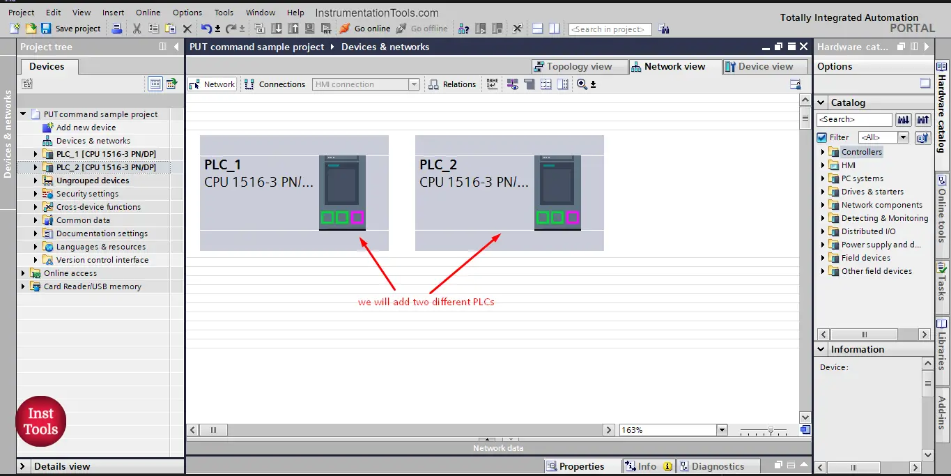
picture 1. Add the local and partner PLCs.
What I need now is to configure PLC_2, the one that will receive the data to be able to receive this data. And PLC_1 will be used with the PUT command.
The 1st thing I need to do is allow the access of the PUT command to the PLC_2 that will receive the data. See picture 2.
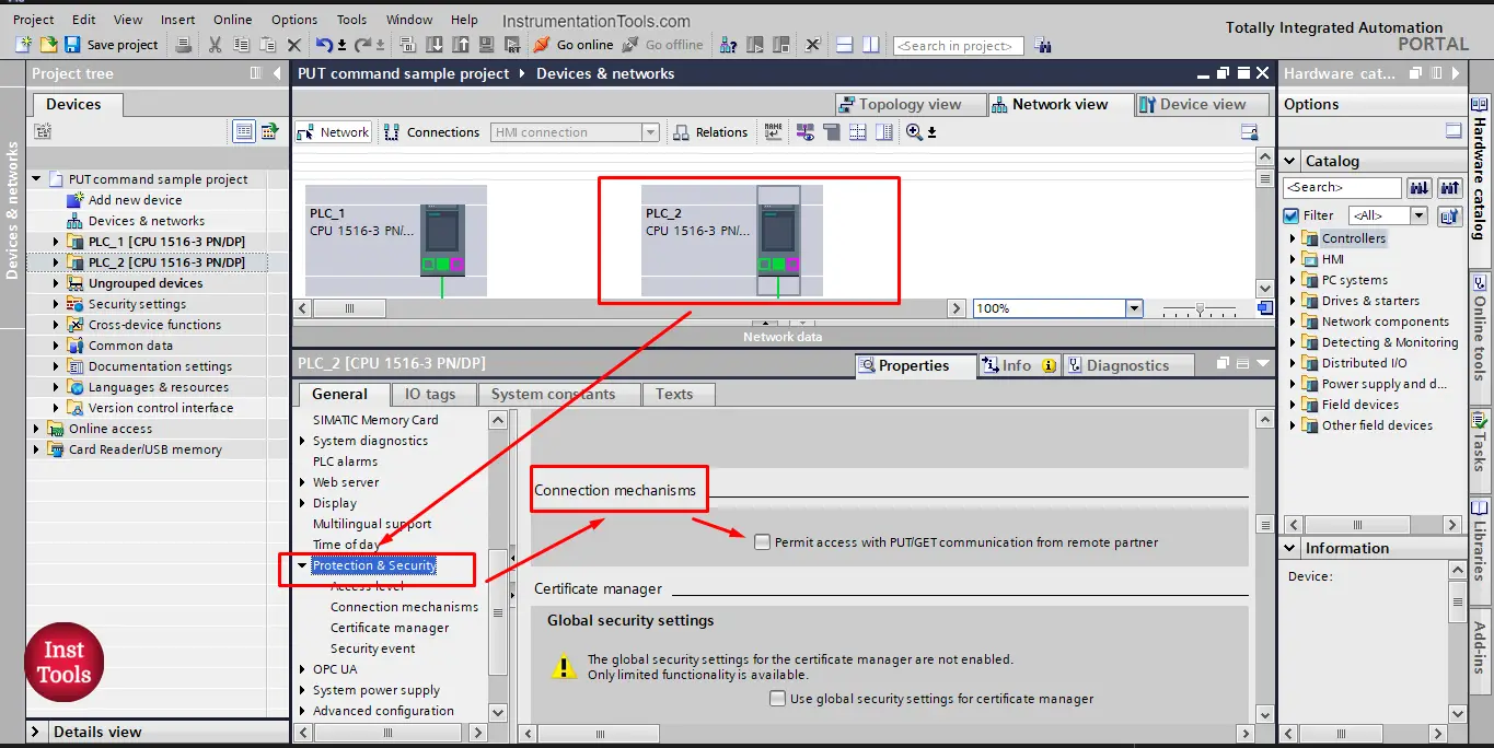
picture 2. Allow PUT command access.
As you see from the picture, we allow the PUT command to access the PLC_2 from the Properties of the PLC_2, in the Protection and Security option, click on the
“Permit access with PUT/GET communication from the remote partner”
Now, I am allowed to put data from any remote partner to PLC_2 using the PUT command.
The 2nd thing is to prepare a space or memory in PLC_2 to the data that will be put in it. We will assume that we want to PUT an integer value into that PLC, so I will prepare a memory according to that. See picture 3.
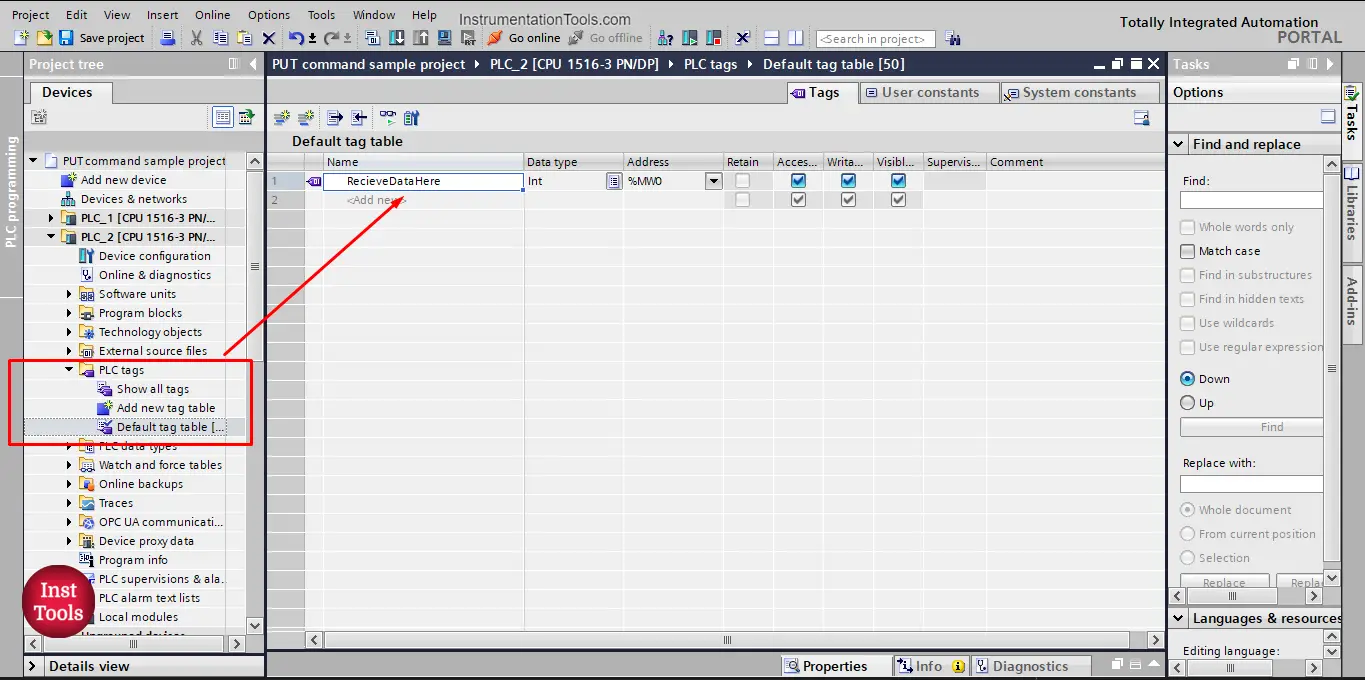
picture 3. Prepare area to receive data.
And that is it; this is the entire configuration you need to prepare from the PLC_2 side to be able to receive data through PUT command.
Next, we set up the data being sent from the PLC_1. We will create a data block to hold the data sent to PLC_2 and inside this data block, we will define an integer tag to be PUT into PLC_2. See picture 4.
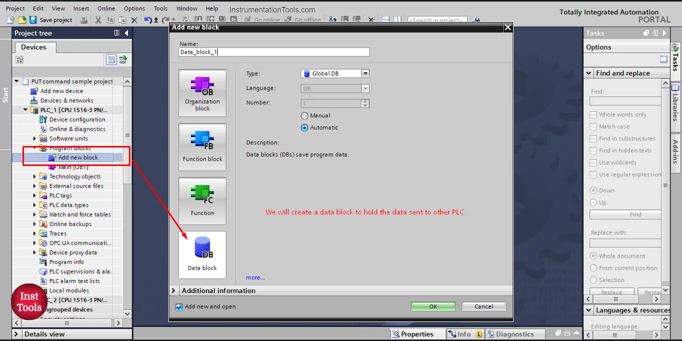
picture 4. Create a data block to hold the sent data.
We defined an integer tag “SendMeToPLC_2” that we want to send to PLC_2. See picture 5.
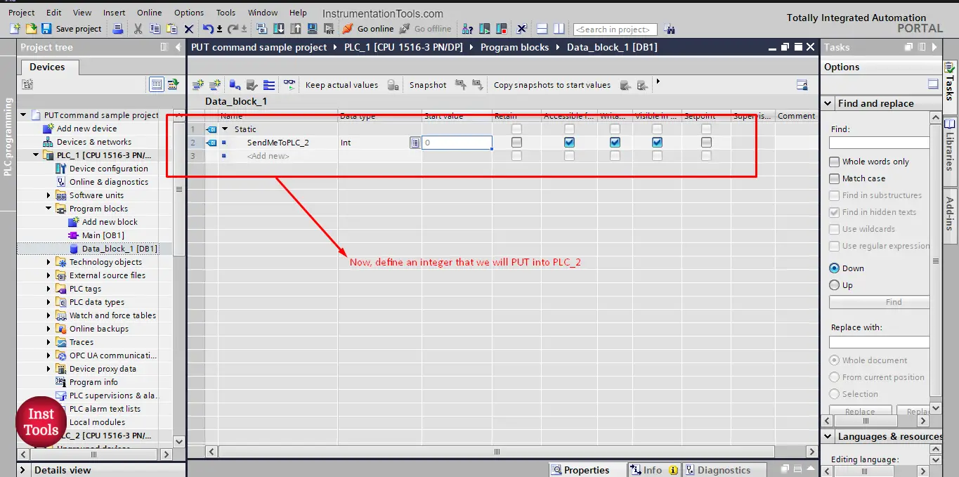
picture 5. Define the data to be sent.
Note that, for PLC_1, we don’t need to allow the access with PUT command option. We activate this feature in the PLC that will receive data, not the PLC that will send it.
Now, let’s use the PUT command in our programming, in the main OB1 we will drag and drop the PUT command FB. See picture 6.
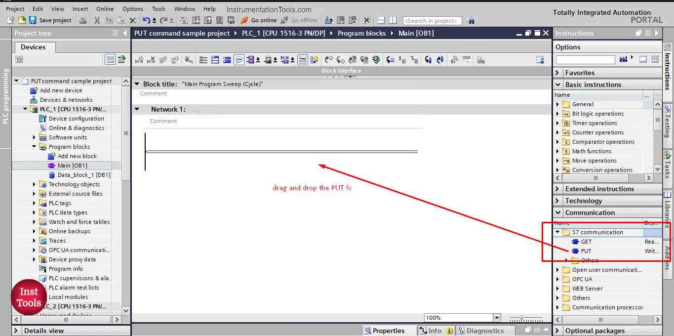
picture 6. Add the PUT command to OB1.
Note that, the PUT command is found in the S7 communication folder, as it is an exclusive function for S7 family PLC, because it involves safety issues. Remember in picture 2 when we allowed the use of PUT command it was in the Security and Protection attribute of the PLC properties as it is related to PLC safety and protection.
The PUT command is essentially a function block, so when adding it to my logic I will be asked to create a data instance. See picture 7.
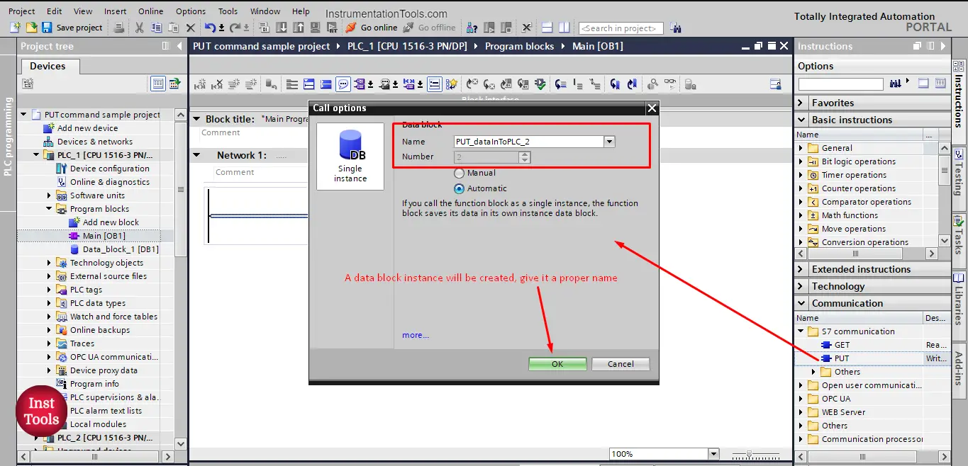
picture 7. Create a data instance for the PUT command.
After you press OK, the PUT command is now added to your PLC logic. See picture 8.
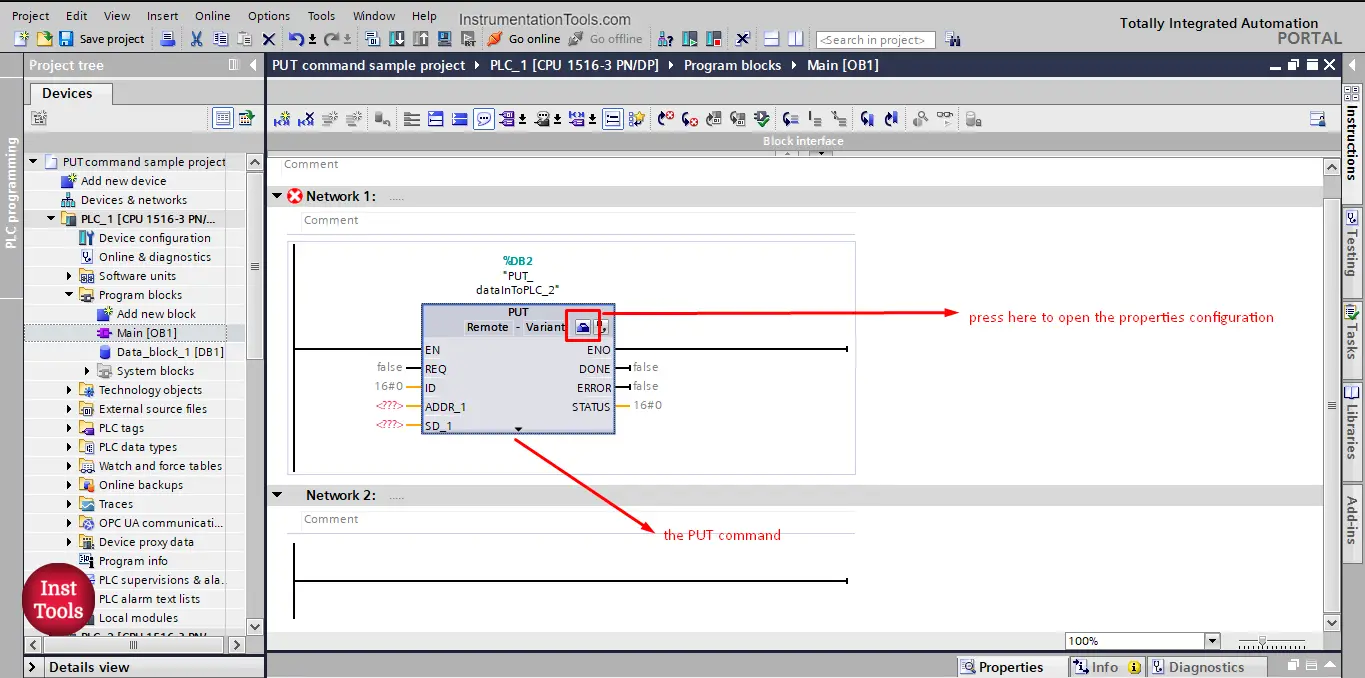
picture 8. PUT command
After we added the PUT command, now we need to configure it, we have two parameters to configure for the PUT command.
- The connection between PLCs
- The block that will be PUT from PLC_1 to PLC_2
To go to the configuration view of the PUT command, press the small blue icon shown in last picture.
In the connection parameter, you will set the communication between the local (PLC_1) and partner (PLC_2) PLCs. See picture 9.
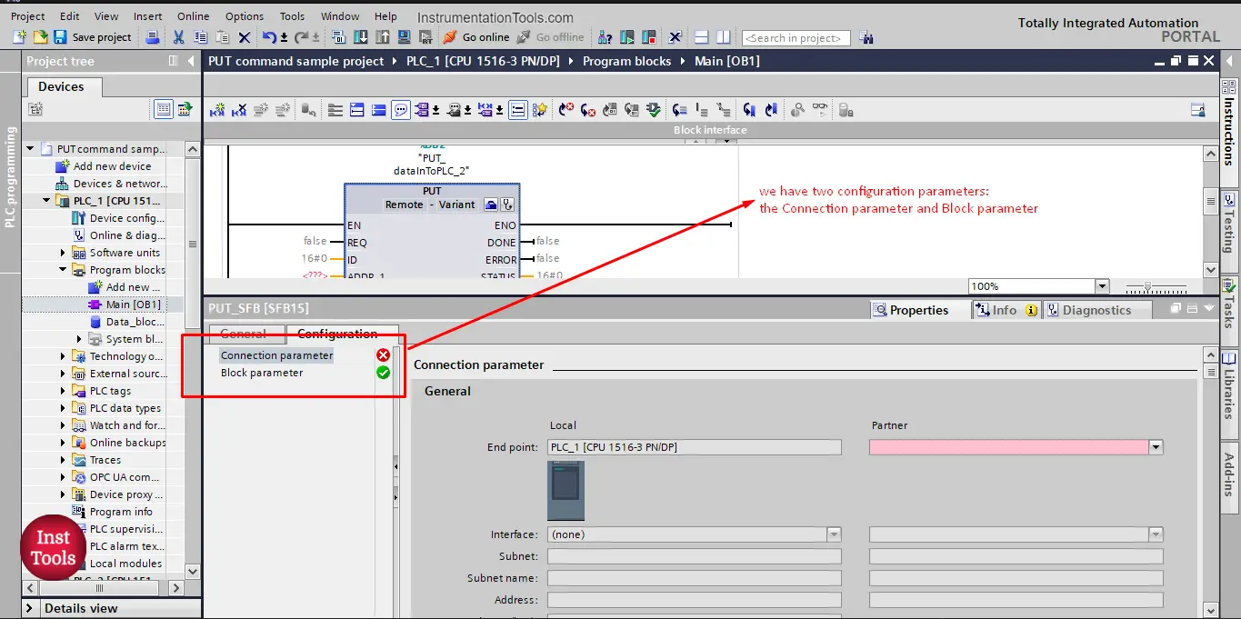
picture 9. Connection parameter.
As you can see, the Local PLC is set to PLC_1 which is the PLC where the PUT command is used. The partner side is still empty and that is where we should assign PLC_2.
If you click on the drop-down list you will have two options for a partner. See picture 10.
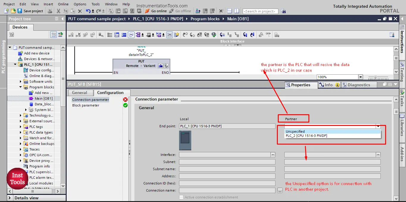
picture 10. Partner connection
The partner is the PLC that will receive the data; you will find that you have two options to select from:
- PLC_2 [CPU 1516-3 PN/DP]
- Unspecified
Because both PLCs are in the same project, when I choose the PLC_2 option, all connection parameters will be automatically filled in. see picture 11.
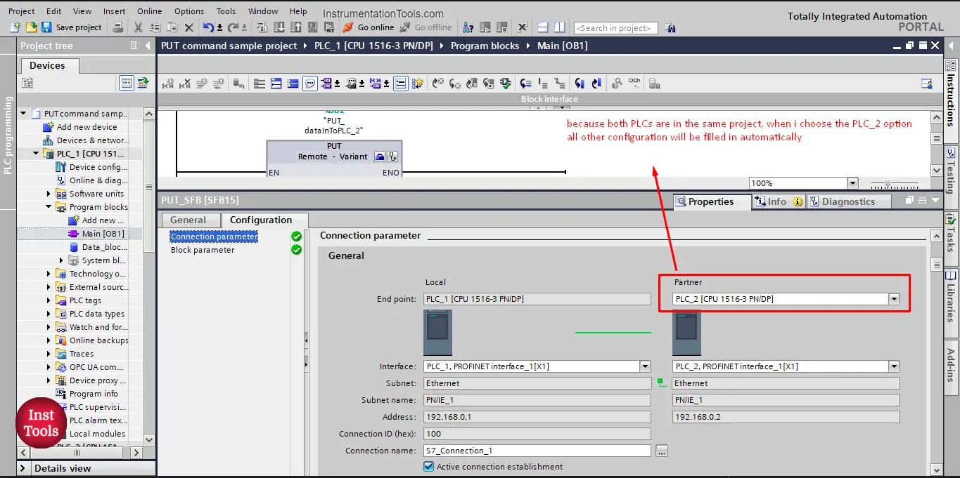
picture 11. PLC_2 as a partner
On the other hand, if the partner PLC is from a different project, then I will choose the Unspecified option, and in that case, I will have to fill in some data such as the Partner PLC’s IP address. See picture 12.
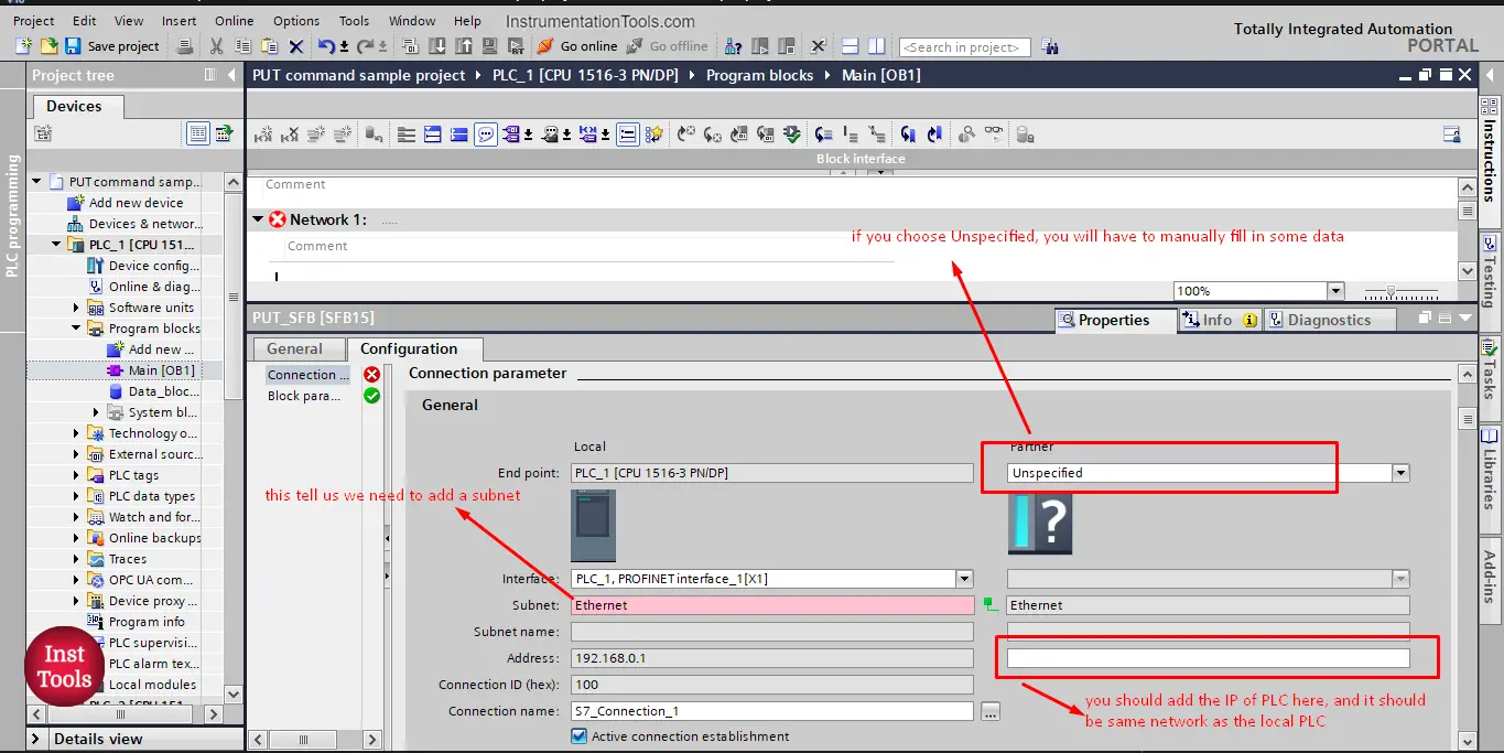
picture 12. Unspecified Partner
As you can see, in that case, I need to fill in some data, such as the IP address and also I need to add a subnet for PLC_1.
To add a subnet for PLC_1 we will go to Profinet properties of the PLC_1 and select add subnet option. See picture 13.
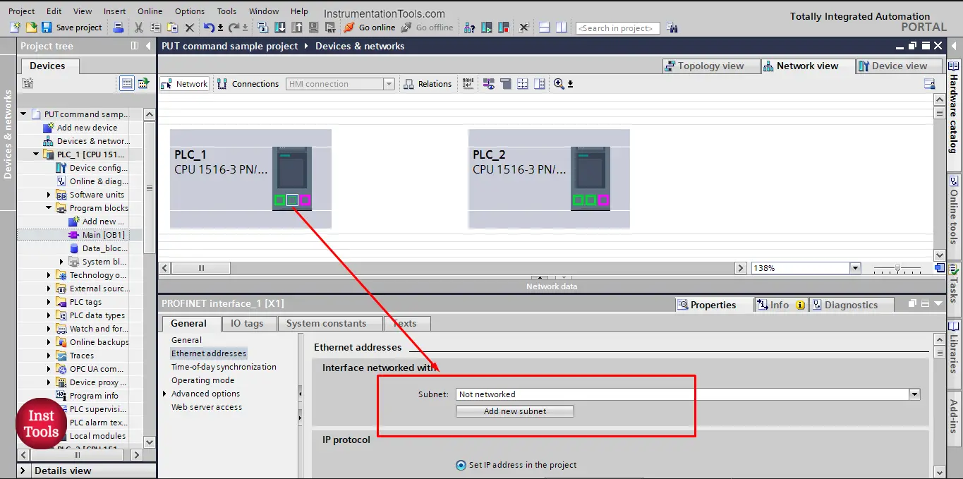
picture 13. Add subnet.
Once that is done, the connection parameter configuration will be done. See picture 14.
The connection name should be Unique for each PUT command you make, TIA Portal will automatically give it a new name, but it is maybe better for you to assign a more proper name for the connection in your project. We here kept it as it is.
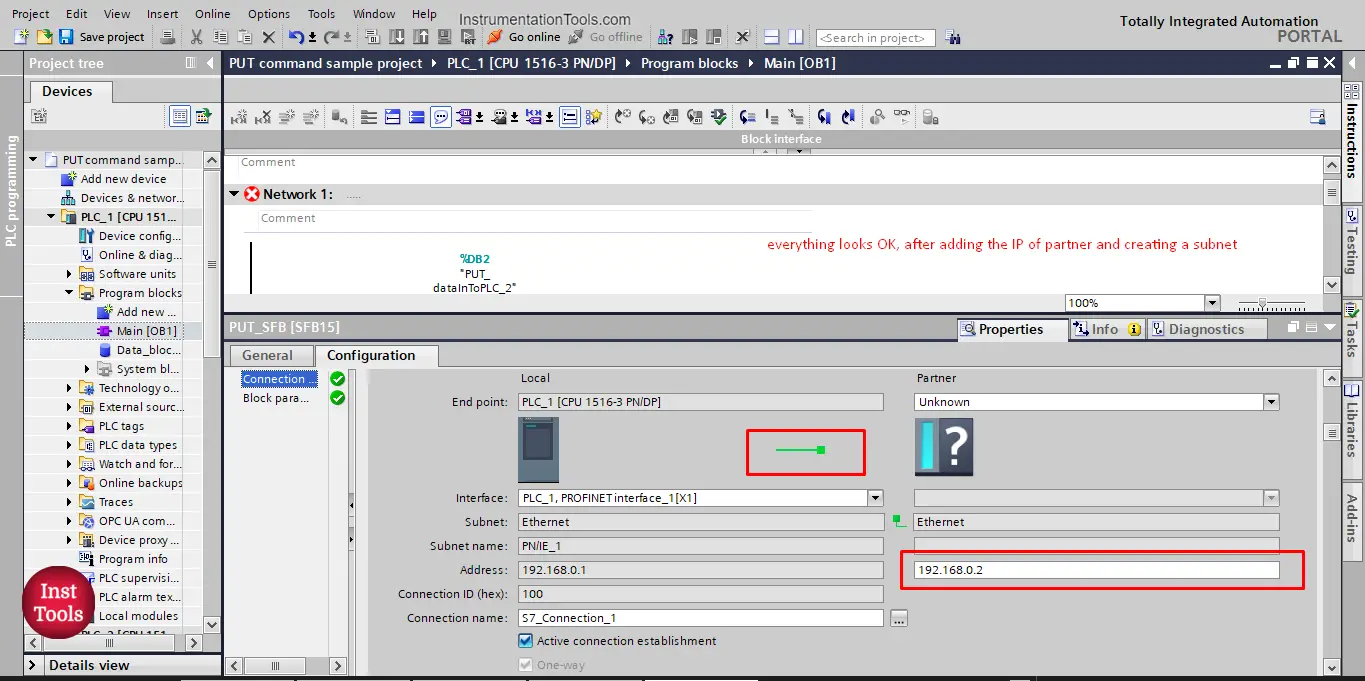
picture 14. Connection parameter is done
The next step in the PUT command configuration is the Block parameter setup.
In these parameters we specify the trigger for the PUT command, meaning what signal will start the PUT command action. And also what data will be put from PLC_1 and where will it be stored in the PLC_2. See picture 15.
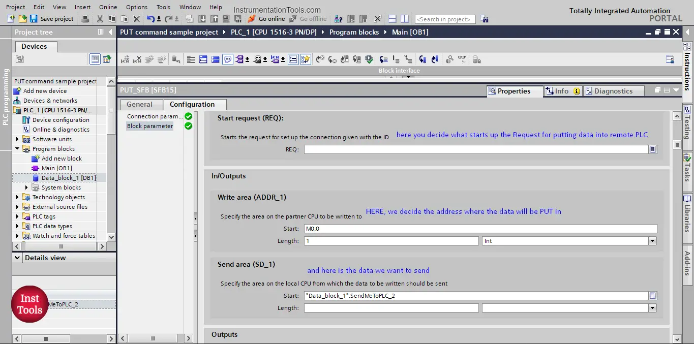
picture 15. Block parameter setup
For the Start Request (REQ) signal we have defined an input tag (SendData %I0.0). And as we mentioned before we have already defined the tag that will be send to PLC_2 and where it will be stored inside the PLC.
Completing the block parameter configuration will conclude the configuration of the PUT command. See picture 16.
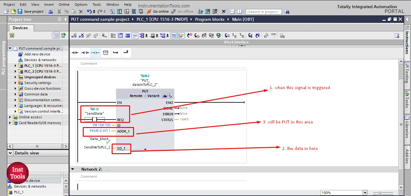
picture 16. Calling of a PUT command
So, in summary, when the REQ signal is triggered, the data in SD_1 will be sent to ADDR_1.
Download the project files.
If you liked this article, then please subscribe to our YouTube Channel for Instrumentation, Electrical, PLC, and SCADA video tutorials.
You can also follow us on Facebook and Twitter to receive daily updates.
Read Next:
- Free PLC Training for Students
- Top Embedded Systems Projects
- How to Choose a PLC for a Project?
- What is Multi-touch Technology?
- Cybersecurity Projects for Students