Inst ToolsInst ToolsInst Tools
  • Ask
  • Courses
  • Videos
  • Q & A
    • Interview
      • Instrumentation
      • Electronics
      • Electrical
      • Practical Questions
    • MCQ
      • Instrumentation MCQ
      • Electrical MCQ
      • Electronics MCQ
      • Control Systems MCQ
      • Analog Electronics MCQ
      • Digital Electronics MCQ
      • Power Electronics MCQ
      • Microprocessor MCQ
      • Multiple Choice Questions
  • EE
    • Electronics
      • Electronics Q & A
      • Electronic Basics
      • Electronic Devices & Circuits
      • Electronics Animation
      • Digital Electronics
    • Electrical
      • Electrical Basics
      • Electrical Q & A
      • Power Electronics
      • Electrical Machines
      • Electrical Animation
      • Power Systems
      • Switchgear & Protection
      • Transmission & Distribution
  • Measure
    • Control Valves
    • Calibration
    • Temperature
    • Pressure
    • Flow
    • Level
    • Analyzers
    • Switches
    • Vibration
    • Solenoid Valve
  • Control
    • PLC Tutorials
    • Control Systems
    • Safety Instrumented System (SIS)
    • Communication
    • Fire & Gas System
  • More
    • Design
    • Tools
    • Animation
    • Basics
    • Formulas
    • Standards
    • TextBooks
    • Common
    • Software
    • Excel Tools
    • Erection & Commissioning
    • Process Fundamentals
    • Videos
    • Books
Search
All rights reserved. Reproduction in whole or in part without written permission is prohibited.
Reading: How Earth Resistance is Measured
Share
Notification Show More
Font ResizerAa
Inst ToolsInst Tools
Font ResizerAa
  • Courses
  • PLC Tutorials
  • Control Systems
Search
  • Ask
  • Courses
  • Videos
  • Q & A
    • Interview
    • MCQ
  • EE
    • Electronics
    • Electrical
  • Measure
    • Control Valves
    • Calibration
    • Temperature
    • Pressure
    • Flow
    • Level
    • Analyzers
    • Switches
    • Vibration
    • Solenoid Valve
  • Control
    • PLC Tutorials
    • Control Systems
    • Safety Instrumented System (SIS)
    • Communication
    • Fire & Gas System
  • More
    • Design
    • Tools
    • Animation
    • Basics
    • Formulas
    • Standards
    • TextBooks
    • Common
    • Software
    • Excel Tools
    • Erection & Commissioning
    • Process Fundamentals
    • Videos
    • Books
Follow US
All rights reserved. Reproduction in whole or in part without written permission is prohibited.
Inst Tools > Blog > Instrumentation Design > How Earth Resistance is Measured

How Earth Resistance is Measured

Last updated: March 16, 2019 8:23 am
Editorial Staff
Instrumentation Design
1 Comment
Share
3 Min Read
SHARE

The term “earth resistivity” expressed in ohm-centimeters (abbreviated ohm-cm) is one basic variable affecting resistance to earth of an electrode system. But the actual value of earth resistivity need not be measured to check the electrode earth resistance. Consider other fields where the value of resistivity is measured; also some of the factors affecting it that are of interest in earth testing.

Earth resistivity measurements can be used conveniently for geophysical prospecting — to locate ore bodies, clays, and water-bearing gravel beneath the earth’s surface. The measurement can also be used to determine depth to bed rock and thickness of glacial drift.

Measurements of earth resistivity are useful also for finding the best location and depth for low resistance electrodes. Such studies are made, for example, when a new electrical unit is being constructed; a generating station, substation, transmission tower, or telephone central office.

Finally, earth resistivity may be used to indicate the degree of corrosion to be expected in underground pipelines for water, oil, gas, gasoline, etc. In general, spots where the resistivity values are low tend to increase corrosion. This same kind of information is a good guide for installing cathodic protection.

How Earth Resistivity is Measured

A four-terminal instrument is used to measure earth resistivity. Now, however, you use four small-sized electrodes driven down to the same depth and equal distances apart in a straight line (Fig. 1). Four separate lead wires connect the electrodes to the four terminals on the instrument, as shown. Hence, the name of this test: the four-terminal method.

Earth Meter Working Principle

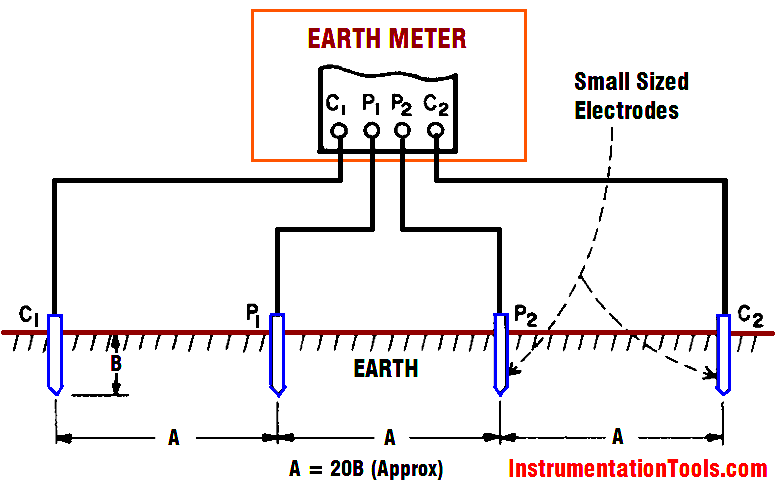
Fig 1 : Four-terminal method of measuring earth resistivity

Dr. Frank Wenner of the U.S. Bureau of Standards (now NIST) developed the theory behind this test in 1915. He showed that, if the electrode depth (B) is kept small compared to the distance between the electrodes (A)1, the following formula applies:

ρ = 2π AR

where ρ is the average soil resistivity to depth A in ohm-cm, π is the constant 3.1416, A is the distance between the electrodes in cm, and R is the Megger earth tester reading in ohms.

In other words, if the distance A between the electrodes is 4 ft, you obtain the average earth resistivity to a depth of 4 ft as follows:

1. Convert the 4 ft to centimeters to obtain A in the formula: 4 x 12 x 2.54 cm = 122 cm

2. Multiply 2 π A to obtain a constant for a given test setup: 2 x 3.14 x 122 = 766 Now, for example, if your instrument reading is 60 Ω, the earth resistivity would be 60 x 766, or 45,960 ohm-cm.

Don't Miss Our Updates
Be the first to get exclusive content straight to your email.
We promise not to spam you. You can unsubscribe at any time.
Invalid email address
You've successfully subscribed !
Draw Wiring of a Pressure Switch to control two lamps
Motor Control Circuits
Thermowell Design Guidelines
Basics of Thermistors, Thermocouples and RTD’s
How to Select a pH or ORP Meter
Share This Article
Facebook Whatsapp Whatsapp LinkedIn Copy Link
Share
1 Comment
  • Mohammad Afroz says:
    December 22, 2016 at 5:32 am

    Dear sir,

    here its written A=20B, instead of 2B ?

    Reply

Leave a Reply Cancel reply

Your email address will not be published. Required fields are marked *

Stay Connected

128.3kFollowersLike
69.1kFollowersFollow
208kSubscribersSubscribe
38kFollowersFollow

Categories

Recent Comments

  • Kamli on Top Free PLC Software
  • Guifty Shimica on Top Non-PLC Certification Courses for Automation Professionals
  • Guifty Shimica on Top Non-PLC Certification Courses for Automation Professionals
  • MIHARITSOA Aina Sitraka on Top Non-PLC Certification Courses for Automation Professionals

Related Articles

Loop Diagram

15 Loop Diagram Questions

Inter Discipline Check (IDC)

What is Inter Discipline Check (IDC)?

Variable Area Flow Meters

All About Variable Area Flow Meters

Control systems in industrial projects

Interactions With Process Control Systems Philosophy

Instrumentation and Control General Specifications

Instrumentation and Control (I&C) General Specifications

Material Take Off (MTO)

What is Material Take Off (MTO)? – Purpose, Components, Uses

Instrumentation and Process Control Project Inputs

Instrumentation and Process Teams Interactions in Design Engineering Companies

Instruments Tapping Points

Instruments Tapping Points – Common versus Individual

More Articles

Active Barrier

What is a Active Barrier ?

Siemens TIA Portal program blocks

Tia Portal – Optimized and Standard Data Block Access

LIC and FIC Controllers

What LIC and FIC Controllers will do?

Ziegler-Nichols closed-loop Tuning - 1

Heuristic PID Tuning Method

Logic Gates Symbols & Truthtables

Logic Gates Animation

overview-of-communication-protocols

Industrial Automation Communication Protocols

CONTROL VALVE CHARACTERISTICS

Difference between Quick Opening, Linear & Equal Percentage Control Valve characteristics

Interview Questions on Control Valves

Interview Questions on Control Valves

Follow US
All rights reserved. Reproduction in whole or in part without written permission is prohibited.
Welcome Back!

Sign in to your account

Username or Email Address
Password

Lost your password?