Inst ToolsInst ToolsInst Tools
  • Courses
  • Videos
  • Q & A
    • Interview
      • Instrumentation
      • Electronics
      • Electrical
      • Practical Questions
    • MCQ
      • Instrumentation MCQ
      • Electrical MCQ
      • Electronics MCQ
      • Control Systems MCQ
      • Analog Electronics MCQ
      • Digital Electronics MCQ
      • Power Electronics MCQ
      • Microprocessor MCQ
      • Multiple Choice Questions
  • EE
    • Electronics
      • Electronics Q & A
      • Electronic Basics
      • Electronic Devices & Circuits
      • Electronics Animation
      • Digital Electronics
    • Electrical
      • Electrical Basics
      • Electrical Q & A
      • Power Electronics
      • Electrical Machines
      • Electrical Animation
      • Power Systems
      • Switchgear & Protection
      • Transmission & Distribution
  • Measure
    • Control Valves
    • Calibration
    • Temperature
    • Pressure
    • Flow
    • Level
    • Analyzers
    • Switches
    • Vibration
    • Solenoid Valve
  • Control
    • PLC Tutorials
    • Control Systems
    • Safety Instrumented System (SIS)
    • Communication
    • Fire & Gas System
  • More
    • Design
    • Tools
    • Animation
    • Basics
    • Formulas
    • Standards
    • TextBooks
    • Common
    • Software
    • Excel Tools
    • Erection & Commissioning
    • Process Fundamentals
    • Videos
    • Books
Search
All rights reserved. Reproduction in whole or in part without written permission is prohibited.
Reading: Instrumentation Basics – Range Conversion Formula and Examples
Share
Notification Show More
Font ResizerAa
Inst ToolsInst Tools
Font ResizerAa
  • Courses
  • PLC Tutorials
  • Control Systems
Search
  • Courses
  • Videos
  • Q & A
    • Interview
    • MCQ
  • EE
    • Electronics
    • Electrical
  • Measure
    • Control Valves
    • Calibration
    • Temperature
    • Pressure
    • Flow
    • Level
    • Analyzers
    • Switches
    • Vibration
    • Solenoid Valve
  • Control
    • PLC Tutorials
    • Control Systems
    • Safety Instrumented System (SIS)
    • Communication
    • Fire & Gas System
  • More
    • Design
    • Tools
    • Animation
    • Basics
    • Formulas
    • Standards
    • TextBooks
    • Common
    • Software
    • Excel Tools
    • Erection & Commissioning
    • Process Fundamentals
    • Videos
    • Books
Follow US
All rights reserved. Reproduction in whole or in part without written permission is prohibited.
Inst Tools > Blog > Formulas > Instrumentation Basics – Range Conversion Formula and Examples

Instrumentation Basics – Range Conversion Formula and Examples

In this article, you will learn the instrumentation basics and transmitter range conversion formula, and industry examples.

Last updated: June 21, 2022 6:26 pm
Editorial Staff
Formulas
2 Comments
Share
5 Min Read
SHARE

We encounter many transmitters in daily activities like preventive maintenance, breakdown, or commissioning activities.

Contents
Instrumentation BasicsInstrument Range Conversion – Method 1Instrument Range Conversion – Method 2

We may need to convert any given transmitter range to other range like from (0oC – 100oC) to (4 mA – 20 mA) or (0 kg/cm2 – 10 kg/cm2) to (3 psi – 15 psi) or (0 mmH2O – 2000 mmH2O) to (0% – 100%), etc.

Instrumentation Basics
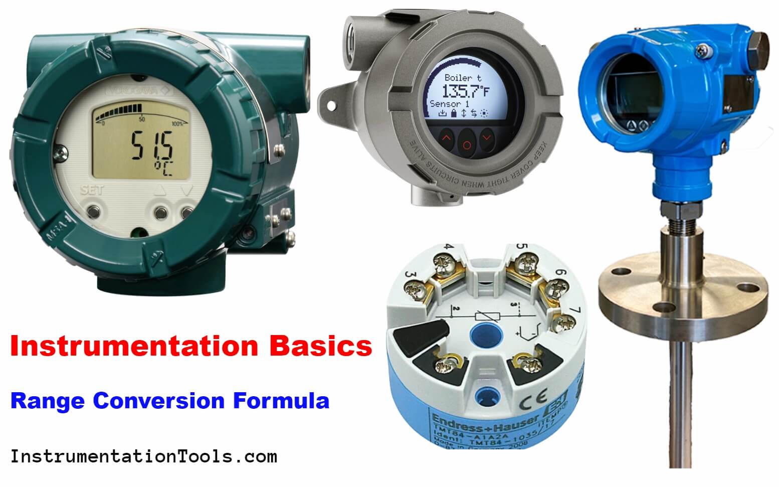
Instrumentation Basics - Range Conversion Formula and Examples

All the above conversions are easy to implement. But now think of a case in which you are supposed to convert from (-250oC to 150oC) to (4 mA to 20 mA) or any such instrument range which has uneven starting and endpoints.

Don’t worry friends, in this article we will learn two methods to convert the value from one range to another range.

Instrument Range Conversion – Method 1

This method might be known to many engineers who are reading this article. But still, we don’t use it frequently because we often forget the formula.

Every transmitter range has two parameters which are LRV and URV. Here LRV means lower range value and URV means upper range value.

Let us recall the method. Suppose the first range is having LRV and URV as LRV_1 and URV_1 and another range has LRV_2 and URV_2.

Desired values are Value_1 and Value_2 in both ranges.

So, we use the below formula:

Range Conversion Formula

Let us see an example.

Suppose range one is 0 kg/cm2 – 100 kg/cm2

Range two is 4 mA to 20 mA

What will be value corresponding to 25 kg/cm2? (in milli amps)

Here Value_1 = 25

LRV_1 = 0

URV_1 = 100

Value_2 = to be calculated

LRV_2 = 4

URV_2 = 20

Put these values into the formula

(25-0) / (100-0) = ((Value_2) – 4) / (20-4)

25/100 = (Value_2 – 4) / 16

0.25 = (Value_2 – 4) / 16

Value_2 – 4 = 0.25 x 16

Value_2 = 4 + 4

Solving this equation, we get

Value_2 = 8

Hence for 25 kg/cm2, we get 8 mA as a proportional value.

This was quite an easy calculation that can even be done without using this formula.

Now have a look at the below example.

Range one: -70 o C to 190 o C

Range two: 4 mA to 20 mA

What will be the value corresponding to 50 o C? (in milli amps)

Put all values in our standard equation.

(50-(-70)) / (190-(-70)) = ((Value_2)-4) / (20-4)

120/260 = (Value_2 – 4)/16

0.4615 = (Value_2 – 4)/16

Value_2 – 4 = (0.4615 x 16)

Value_2 = 7.384 + 4

Solving this equation, we get

Value_2 = 11.384 mA

This is the first method.

Now let us see the second method which is for those who do not want to remember the formula.

Instrument Range Conversion – Method 2

Let us see this method by taking an instrument example. Let us take the above example only

Range one: -70oC to 190oC

Range two: 4 mA to 20 mA

We need to calculate the equivalent milli amperes for the value of 50oC

First, calculate how much % is 50oC in the range of -70oC to 190oC.

The range is 260oC

For this we will use a simple formula :

50-(-70)  —->  260

     ?      <—-  100

We have to take 50-(-70) because we want absolute value from LRV.

We get,

(100*120)/260 = 46.1538 %

Now we need a 46.1538% value for the 4 mA to 20 mA range

Divide the above value by 100. (46/100 = 0.461538)

Here 16 is the difference between URV and LRV.

So, multiply 0.461538 by 16. We get 7.3846.

Now add this value to our LRV. (7.3846 + 4)

We get 11.3846 mA which is our required value.

This is how we can convert values from one range to another.

If you liked this article, then please subscribe to our YouTube Channel for Instrumentation, Electrical, PLC, and SCADA video tutorials.

You can also follow us on Facebook and Twitter to receive daily updates.

Read Next:

  • 4 to 20 mA Formula
  • Calculate Process Variable
  • How to do 4-20mA Conversion
  • Raw Counts to Engineering Units
  • Turbine Flow meter Coefficient
Don't Miss Our Updates
Be the first to get exclusive content straight to your email.
We promise not to spam you. You can unsubscribe at any time.
Invalid email address
You've successfully subscribed !

Recommended Articles

PLC Problems Troubleshooting
Turbine Flow Meter Coefficient and Scaling Factor
Instrument Percent of Span Error
Displacer Level Measurement Calculations
PLC Analog Input Conversion Formula
Formula for Percentage to Process Variable Conversion
Share This Article
Facebook Whatsapp Whatsapp LinkedIn Copy Link
Share
2 Comments
  • Rafael Ramirez says:
    June 16, 2022 at 12:43 am

    I would love more training on all these courses

    Reply
  • JULFIHAR says:
    March 17, 2023 at 2:11 am

    Thermocouple k and j type
    . I know mv , how to find degree ? Formula
    I know degree , how to find mv ? Formula
    Please.

    Reply

Leave a Reply Cancel reply

Your email address will not be published. Required fields are marked *

Stay Connected

128.3kFollowersLike
69.1kFollowersFollow
208kSubscribersSubscribe
38kFollowersFollow

Categories

Recent Comments

  • William Snyder on Top Non-PLC Certification Courses for Automation Professionals
  • Kamli on Top Free PLC Software
  • Guifty Shimica on Top Non-PLC Certification Courses for Automation Professionals
  • Guifty Shimica on Top Non-PLC Certification Courses for Automation Professionals

Related Articles

Field Transmitter Range Calculation

Transmitter Turndown Ratio, Set Span and Zero Span

Flow Transmitter Output Current Calculation

Calculate Flow Transmitter Output Current

How is pressure drop calculated through a valve?

How is Pressure Drop Calculated through a Valve ?

Formulas to calculate ma from PV

Formulas to calculate mA from PV, LRV and URV

4-20mA VFD Drive Formula

4-20mA Linear Conversion Calculation for VFD Drive (Formula)

4-20mA to Process Variable conversion

Formula to Calculate Process Variable from 4-20mA

Formula for Linear mA to Square root mA conversion

Open Tank DP Level Measurement

Open Tank DP Level Transmitter Calculations

More Articles

Steam Pressure Control

Steam Pressure Control

Machine Learning

Difference Between Machine Learning and Artificial Intelligence?

Bellow Principle

Bellows

Pneumatic Valves and Cylinders Sizing

Pneumatic Valves and Cylinders Sizing – Part 2

Electronics and Instrumentation Students Quiz

Electronics and Instrumentation Students Quiz

Basic Control Systems Questions

14 Basic Control Systems Questions for Interview Preparation

Digital Electronics Multiple Choice Questions

Integrated Injection Logic (IIL) Objective Questions

Testing and Validation in PLC Development

Testing and Validation in PLC Development

Follow US
All rights reserved. Reproduction in whole or in part without written permission is prohibited.
Welcome Back!

Sign in to your account

Username or Email Address
Password

Lost your password?