Inst ToolsInst ToolsInst Tools
  • Courses
  • Automation
    • PLC
    • Control System
    • Safety System
    • Communication
    • Fire & Gas System
  • Instrumentation
    • Design
    • Pressure
    • Temperature
    • Flow
    • Level
    • Vibration
    • Analyzer
    • Control Valve
    • Switch
    • Calibration
    • Erection & Commissioning
  • Interview
    • Instrumentation
    • Electrical
    • Electronics
    • Practical
  • Q&A
    • Instrumentation
    • Control System
    • Electrical
    • Electronics
    • Analog Electronics
    • Digital Electronics
    • Power Electronics
    • Microprocessor
Search
  • Books
  • Software
  • Projects
  • Process
  • Tools
  • Basics
  • Formula
  • Power Plant
  • Root Cause Analysis
  • Electrical Basics
  • Animation
  • Standards
  • 4-20 mA Course
  • Siemens PLC Course
Reading: What is Gas Meter and Regulating Station?
Share
Notification Show More
Font ResizerAa
Inst ToolsInst Tools
Font ResizerAa
  • Courses
  • Design
  • PLC
  • Interview
  • Control System
Search
  • Courses
  • Automation
    • PLC
    • Control System
    • Safety System
    • Communication
    • Fire & Gas System
  • Instrumentation
    • Design
    • Pressure
    • Temperature
    • Flow
    • Level
    • Vibration
    • Analyzer
    • Control Valve
    • Switch
    • Calibration
    • Erection & Commissioning
  • Interview
    • Instrumentation
    • Electrical
    • Electronics
    • Practical
  • Q&A
    • Instrumentation
    • Control System
    • Electrical
    • Electronics
    • Analog Electronics
    • Digital Electronics
    • Power Electronics
    • Microprocessor
Follow US
All rights reserved. Reproduction in whole or in part without written permission is prohibited.
Inst Tools > Blog > Flow Measurement > What is Gas Meter and Regulating Station?

What is Gas Meter and Regulating Station?

In this article, we will discuss about the gas meter and regulating station for the natural gas distribution system.

Last updated: December 14, 2021 11:30 am
Editorial Staff
Flow Measurement
1 Comment
Share
5 Min Read
SHARE

In this article, we will discuss about the gas meter and regulating station for commercial usage. This station is used for the natural gas distribution systems.

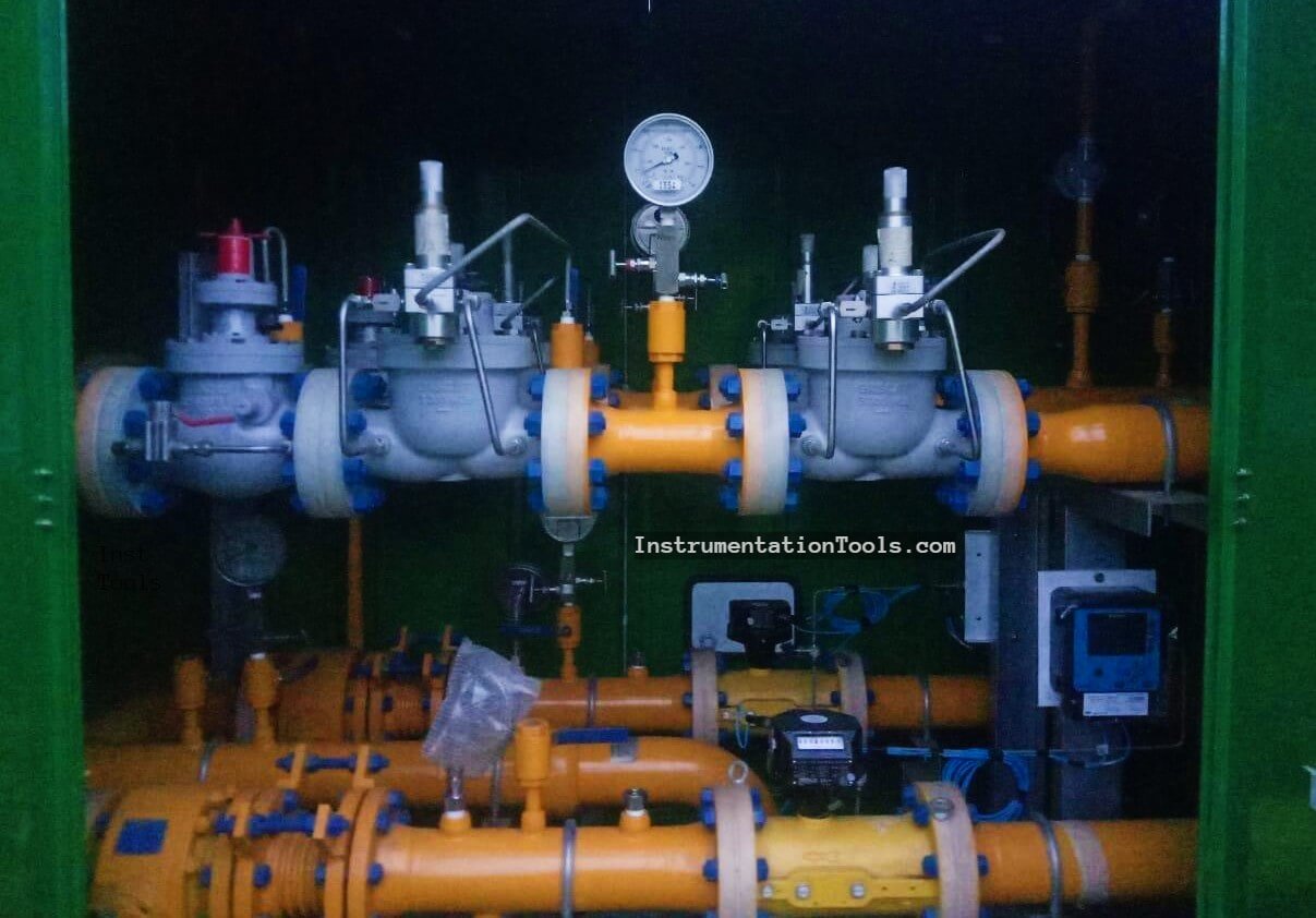
This is the Meter Regulating Station in Indonesia and is owned by Indonesia National Gas Company (PGN) or Perusahaan Gas Negara.

What is Gas Meter and Regulating Station

Before we discuss this plant in more detail, we must understand about the gas distribution system.

Gas Distribution System P&ID

Gas Distribution System

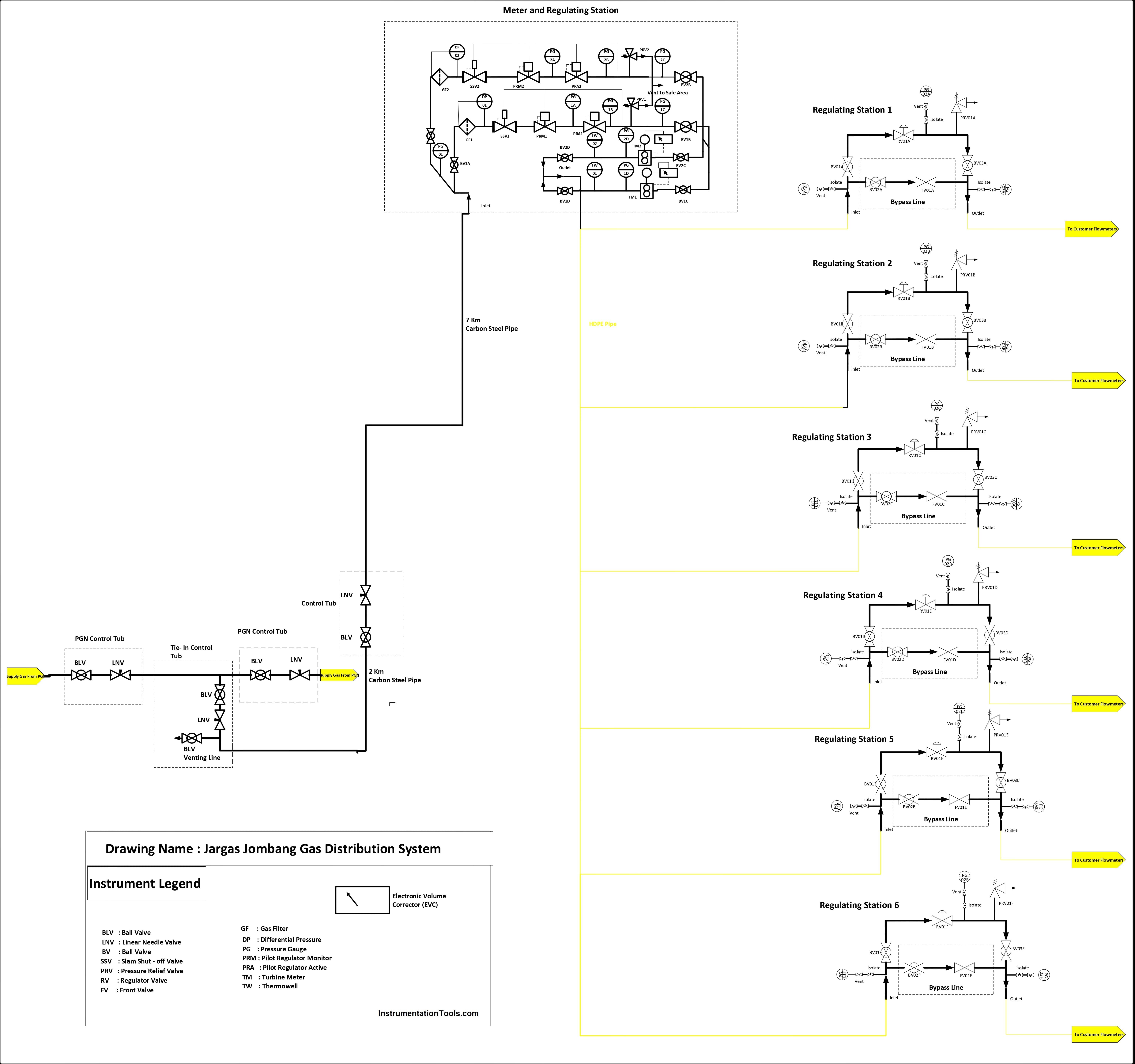
From the drawing, we know that the Meter Regulating Station (M/RS) is located after the tie-in line from the PGN line.

The gas is about 5 – 30 Barg from the tie-in line for the M/RS inlet. In this M/RS the gas is filtered, regulated, and measured until this outlet is 1 – 4 Barg.

So, what makes the gas is at pressure-reduced conditions? So, let’s check for the part of the P&ID at the M/RS section. And knowing the datasheet from these stations.

Metering Regulating Station

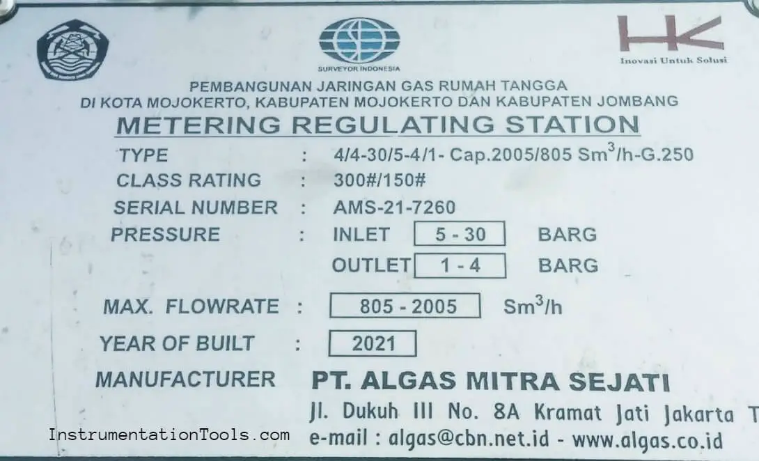
On the datasheet, we know the maximum flow rate, pressure, and G-Size from Turbine Meter (G-250).

Turbine Meter P&ID

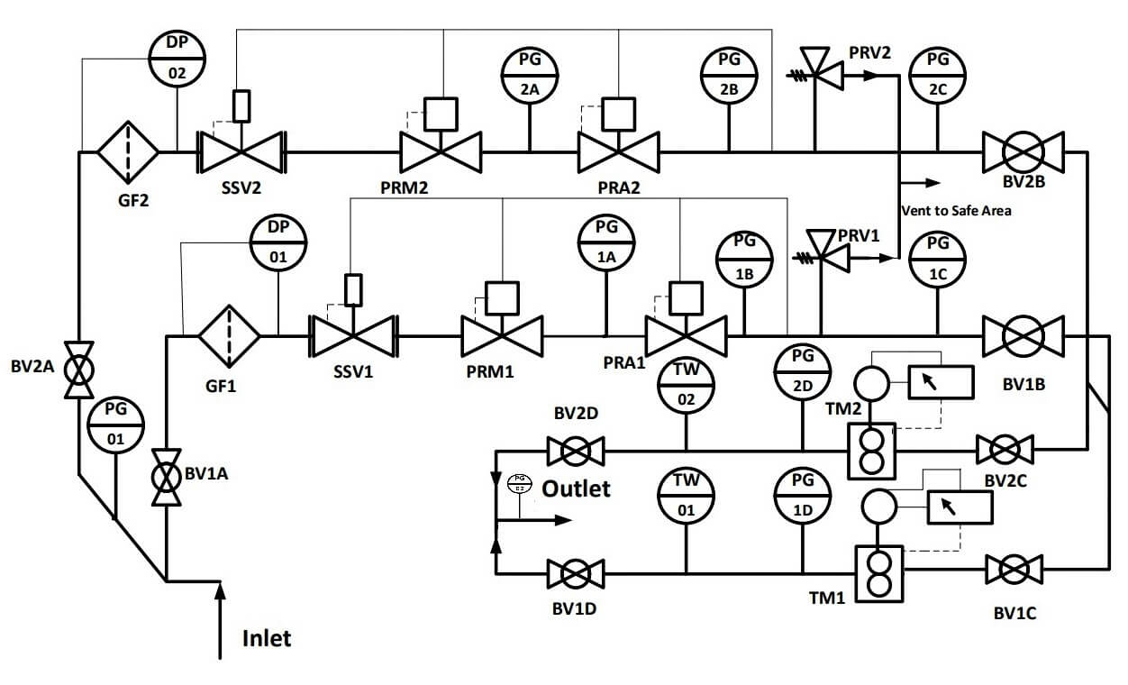
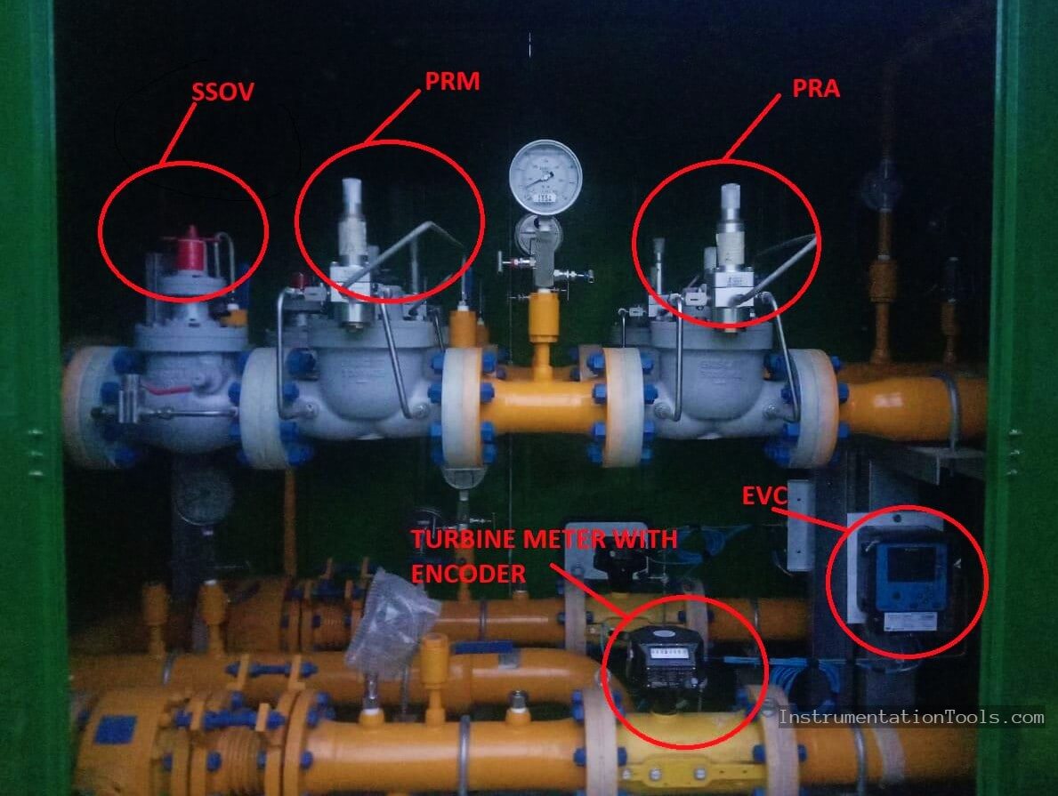
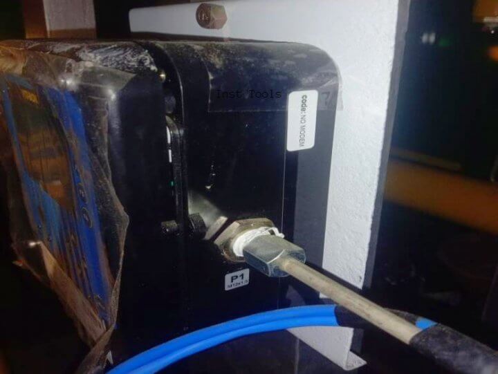
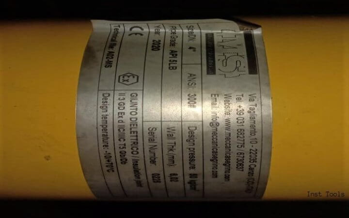
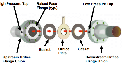
The first process is gas in from the inlet (insulation joint). There are 2 lines at upstream and downstream. We can know the pressure inlet from PG-01.

The gas is in via BV1/2A (Ball Valve). And after that, the gas passes the filter GF1/2 (Gas Filter) to filter the gas from impurities. And measured with the differential pressure gauge (DP).

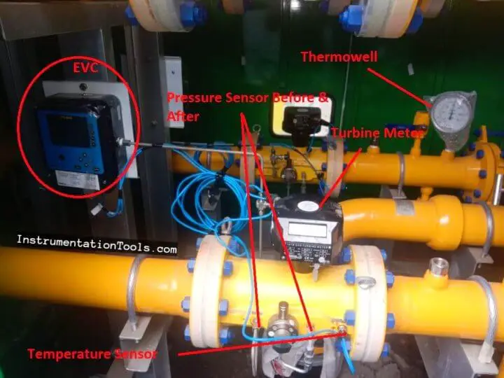
The gas is about 5 – 30 Barg. And after the DP gauge, the gas is regulated by SSOV (Slam-Shut Off Valve) to 4,5 Barg, Pilot Regulator Monitor (PRM) 4,1 Barg, and Pilot Regulator Active (PRA) 4 Barg and will go to the downstream section to be calculated with Electronic Volume Corrector (EVC) who’s connected with the pressure sensor, temperature sensor, a turbine meter with encoder to record the flowrate.

After that, the gas measured this temperature with thermowell too (TW1/2) and go to outlet insulation joint section and measured by PG 02 (The author forget to draw the outlet pressure gauge, so the draw on this P&ID is small than other instruments).

Turbine Meter Custody Transfer

There are the PRV1/2 (Pressure Relief Valve) to relieve the pressure if there is overpressure at the upstream pressure.

It usually happened if the usage of the gas is suddenly decreased. The PRV is set on 4.3 Barg.

Gas-volume Conversion Device PTZ Box

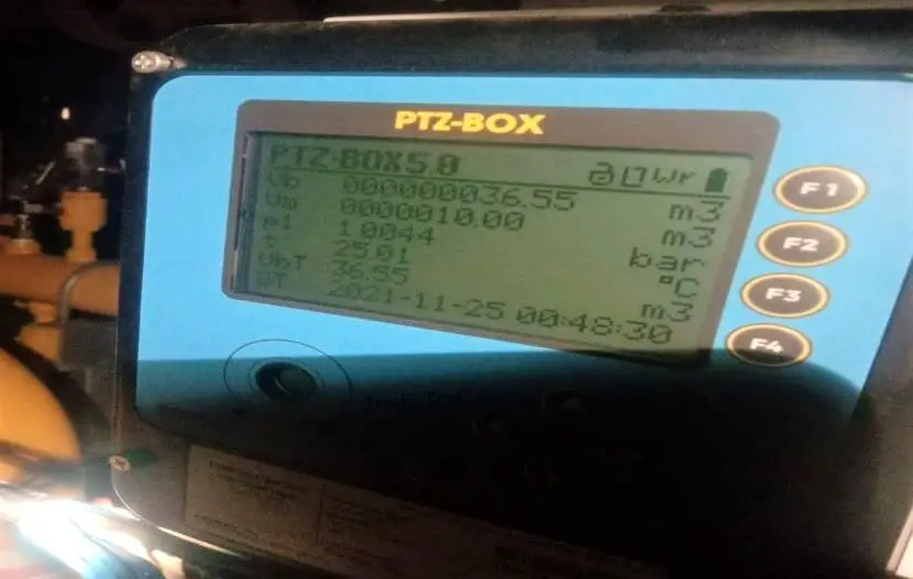
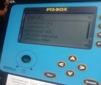
The picture above is showing about the parameters is measured by EVC. There are Vm (Volume at measurement conditions or nPsiG) and Vb (Volume at base conditions or 0Psig).

So the EVC is used to convert the gas flow rate from measured condition to base condition. In this case, gas compressibility law is available.

PV = nRT

If the gas temperature is low, so the pressure and the volume will be decreased than at higher temperature conditions.

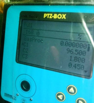
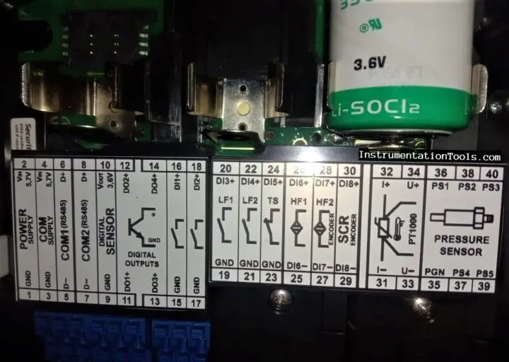
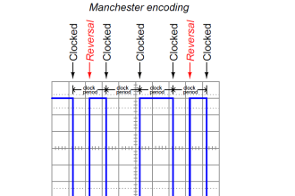
This equipment is equipped with a pressure sensor, temperature sensor (PT-100), and IGTM turbine meter G-250. It can be added by NAMUR sensor and Encoder. And we can monitor the gas composition such as C1, C2, C3, C4,….until H2.

The equipment is featured by RS485 communication. So the gas value from EVC is can be collected and monitored with SCADA wireless (using GPRS) or not (using RS485).

Gas Composition PTZ Box
Gas Composition
EVC Wiring Configuration
PTZ Box
EVC Inputs Configuration
EVC Pressure Sensor Inputs
Custody Metering Installation
EVC Installation Configuration
Custody Meter Insulation Joint at Inlet and Outlet Stream
Insulation Joint at Inlet and Outlet Stream

To get good performance for the measure and regulating process at this gas distribution system, the equipment at the M/RS should be on good maintenance.

Author: Ramadhani Ichlasul Amal

Ramadhani Ichlasul Amal

Bachelor of Applied Instrumentation Engineering Sepuluh Nopember Institute of Technology (ITS). And now at Jargas Jombang Operational and Maintenance Team.

Don't Miss Our Updates
Be the first to get exclusive content straight to your email.
We promise not to spam you. You can unsubscribe at any time.
Invalid email address
You've successfully subscribed !

Continue Reading

Coriolis Flow Meter Uncertainty and Inaccuracy
Types of Orifice Plates & Orifice Plate Tappings
Why Viscosity is Not Included in the Orifice Equation?
Laminar Flow Meter Working Principle
Weirs and Flumes Flow Measurement
Flare Ultrasonic Flow Meter – SOPAS Engineering Tool
Share This Article
Facebook Whatsapp Whatsapp LinkedIn Copy Link
Share
1 Comment
  • RG says:
    July 12, 2023 at 8:44 am

    Terima kasih, sangat membantu 👍

    Reply

Leave a Reply Cancel reply

Your email address will not be published. Required fields are marked *

Stay Connected

128.3kFollowersLike
69.1kFollowersFollow
210kSubscribersSubscribe
38kFollowersFollow

Categories

Explore More

Types of Vortex Flow Meter Sensors
Working Principle of Vortex Flow Meter
Transit Time Flow Meter – Types, Advantages, Disadvantages
Target Flow Meter – Working Principle, Advantages, Disadvantages
Flow Meter Calibration
What is a Square Root Extractor? – DP Flow Measurement
Flow Standards
Gas and Liquid Measurement: Processes and Solutions for the Industrial Sector

Keep Learning

Turbine Flow Meter Calibration

How to do Turbine Flow Meter Verification?

Particle Image Velocimetry (PIV) Principle

Particle Image Velocimetry (PIV) Principle

Circular Chart Recorder

How to Read Circular Chart Recorder for Flow Measurement?

What is Averaging Pitot Tube

What is an Averaging Pitot Tube? – Principle, Advantages

Open Channel Flow Measurement Animation

Open Channel Flow Measurement Principle

Advantages and Disadvantages of Flow Measurement Techniques

Advantages & Disadvantages of Different Flow Meters

Orifice Flow Measurement Formula

Basics of Flow Measurement

Pressure and Temperature Compensation for Flow Transmitter

Why Pressure & Temperature Compensation required for Orifice Flow Meters ?

Learn More

Electronic Force Balance Pressure Transmitter

Electronic Force Balance Pressure Transmitter

pH Analyzer Calibration and Troubleshooting

pH Analyzer Calibration and Troubleshooting

PIN Diode Working Principle

PIN Diode Working Principle

PLC Program for motor operation based on time cycle

PLC Motor Operation based on Time Cycle Sequence – Program

Control Valve Positioner Working Principle

Control Valve Positioner Working Principle

Generator Protection Interview Questions

Generator Protection Interview Questions & Answers

Studio 5000 Tutorial PLC Programming for Digital Alarms

Studio 5000 Tutorial: PLC Programming for Digital Alarms

Parallel Circuit

Parallel Circuit

Menu

  • About
  • Privacy Policy
  • Copyright

Quick Links

  • Learn PLC
  • Helping Hand
  • Part Time Job

YouTube Subscribe

Follow US
All rights reserved. Reproduction in whole or in part without written permission is prohibited.
Welcome Back!

Sign in to your account

Username or Email Address
Password

Lost your password?