Inst ToolsInst ToolsInst Tools
  • Ask
  • Courses
  • Videos
  • Q & A
    • Interview
      • Instrumentation
      • Electronics
      • Electrical
      • Practical Questions
    • MCQ
      • Instrumentation MCQ
      • Electrical MCQ
      • Electronics MCQ
      • Control Systems MCQ
      • Analog Electronics MCQ
      • Digital Electronics MCQ
      • Power Electronics MCQ
      • Microprocessor MCQ
      • Multiple Choice Questions
  • EE
    • Electronics
      • Electronics Q & A
      • Electronic Basics
      • Electronic Devices & Circuits
      • Electronics Animation
      • Digital Electronics
    • Electrical
      • Electrical Basics
      • Electrical Q & A
      • Power Electronics
      • Electrical Machines
      • Electrical Animation
      • Power Systems
      • Switchgear & Protection
      • Transmission & Distribution
  • Measure
    • Control Valves
    • Calibration
    • Temperature
    • Pressure
    • Flow
    • Level
    • Analyzers
    • Switches
    • Vibration
    • Solenoid Valve
  • Control
    • PLC Tutorials
    • Control Systems
    • Safety Instrumented System (SIS)
    • Communication
    • Fire & Gas System
  • More
    • Design
    • Tools
    • Animation
    • Basics
    • Formulas
    • Standards
    • TextBooks
    • Common
    • Software
    • Excel Tools
    • Erection & Commissioning
    • Process Fundamentals
    • Videos
    • Books
Search
All rights reserved. Reproduction in whole or in part without written permission is prohibited.
Reading: #16 PLC Best Practices – Create Trend for Cycle Time on HMI
Share
Notification Show More
Font ResizerAa
Inst ToolsInst Tools
Font ResizerAa
  • Courses
  • PLC Tutorials
  • Control Systems
Search
  • Ask
  • Courses
  • Videos
  • Q & A
    • Interview
    • MCQ
  • EE
    • Electronics
    • Electrical
  • Measure
    • Control Valves
    • Calibration
    • Temperature
    • Pressure
    • Flow
    • Level
    • Analyzers
    • Switches
    • Vibration
    • Solenoid Valve
  • Control
    • PLC Tutorials
    • Control Systems
    • Safety Instrumented System (SIS)
    • Communication
    • Fire & Gas System
  • More
    • Design
    • Tools
    • Animation
    • Basics
    • Formulas
    • Standards
    • TextBooks
    • Common
    • Software
    • Excel Tools
    • Erection & Commissioning
    • Process Fundamentals
    • Videos
    • Books
Follow US
All rights reserved. Reproduction in whole or in part without written permission is prohibited.
Inst Tools > Blog > PLC Tutorials > #16 PLC Best Practices – Create Trend for Cycle Time on HMI

#16 PLC Best Practices – Create Trend for Cycle Time on HMI

Summarize PLC cycle time every 2 to 3 seconds and report to HMI for visualization on a graph using trend.

Last updated: September 22, 2021 6:37 pm
Editorial Staff
PLC Tutorials
No Comments
Share
4 Min Read
SHARE

Summarize PLC cycle time every 2 to 3 seconds and report to HMI for visualization on a graph using trend.

Contents
Trend for PLC Cycle TimeExample
Security ObjectiveTarget Group
MonitoringIntegration / Maintenance Service Provider

Trend for PLC Cycle Time

Cycle times are usually system variables in a PLC and can be used for summarizing in PLC code. Summarization should be done to calculate average, peak, and minimum cycle times. The HMI should trend these values and alert if there are significant changes.

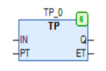
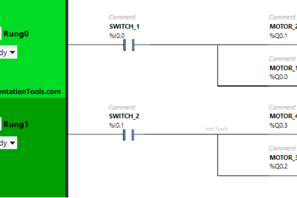
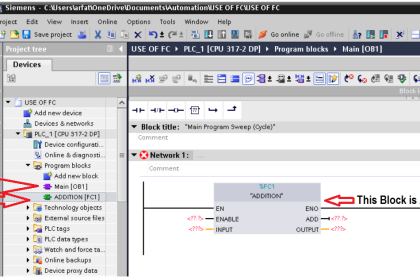
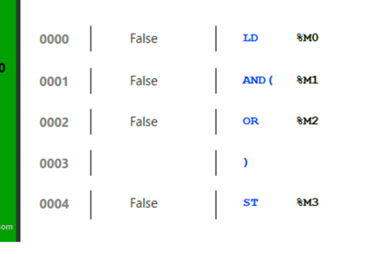
The cycle time is the time it takes to compute each iteration of logic for the PLC. The iterations are the combination of Ladder Diagrams (LD), Function Block Diagrams (FBD), Instruction List (IL), and Structured Text (ST). These logic components may be joined together with the Sequential Function Charts (SFC).

Cycle times should be constant on a PLC unless there are changes to e.g.

  • network environment
  • PLC logic
  • process

Therefore, unusual cycle time changes can be an indicator that PLC logic changed and thus provide valuable information for integrity checks.

Visualizing values over time using a graph provides an intuitive way to draw attention to anomalies which would be harder to notice by just having absolute values.

Types of Scan Time in a PLC

Example

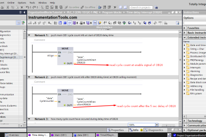
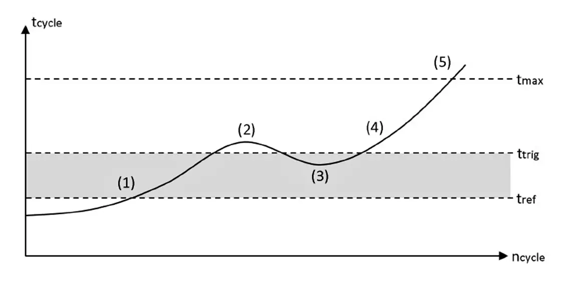
Many PLCs have a “maximum cycle time” monitoring at the hardware level. If the cycle time exceeds the maximum value, the hardware sets the CPU to STOP (5).

Of course, attackers are aware of this and will keep a possible attack code as lean as possible to minimize the impact on the overall cycle time. In an additional software cycle time monitoring program, a reference cycle time tref is defined as base cycle time.

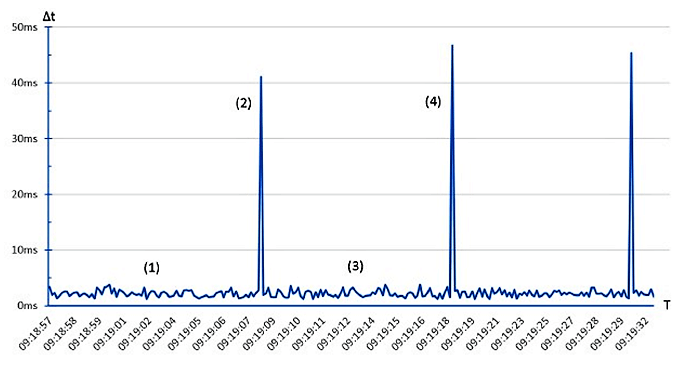
As small fluctuations are natural, an acceptable threshold needs to be defined (1,3) The cycle monitoring is triggered, if the threshold is exceeded (2,4).

Trend for PLC Cycle Time

Any deviance from the reference time can be stored in a log file like this:

log file in PLC

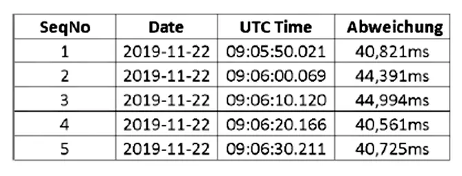
If cycle times are trended to the HMI, heavy CPU loads are visible at a glance.

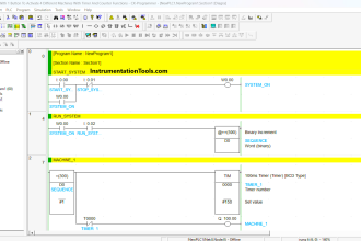
The following example diagram shows a PLC-Program with periodically executed malicious code. (1,3) show acceptable cycle time fluctuations (“noise”) during normal operation, attack code is executed on (2,4) which increase the cycle time.

PLC cycle times are trended to the HMI

Why?

Beneficial for…?Why?
          SecurityAttacks to PLCs include changing its logic, activating a new program, testing new code, loading a new process recipe, inserting auxiliary logic to send messages or activate some feature.

For most PLCs, traditional cryptographic integrity checks are not feasible. However, it’s good to alert if any of the above logic changes happen.

Since cycle times are rather constant under normal circumstances, changes in cycle times are a good indicator that the logic in one of the above logic components has changed.
ReliabilitySee security, but for non-malicious causes.
Maintenance/

References

Standard/frameworkMapping
MITRE ATT&CK ICSTactic:  TA002 – Execution
Technique:  T0873 – Project File Infection
ISA 62443-3-3SR 3.4: Software and information integrity
ISA 62443-4-2EDR 3.2: Protection from malicious code
MITRE CWECWE-754: Improper Check for Unusual or Exceptional Conditions

Source: PLC Security

Don't Miss Our Updates
Be the first to get exclusive content straight to your email.
We promise not to spam you. You can unsubscribe at any time.
Invalid email address
You've successfully subscribed !
Siemens Tia Portal PLC Training Course
Control Algorithms in PLC Programming
Learn about PLC, DCS, RTU, SCADA, and PAC
Use of Regions in SCL Language
Gas Turbine Temperature Alarms using Siemens TIA Portal
Share This Article
Facebook Whatsapp Whatsapp LinkedIn Copy Link
Share
Leave a Comment

Leave a Reply Cancel reply

Your email address will not be published. Required fields are marked *

Stay Connected

128.3kFollowersLike
69.1kFollowersFollow
208kSubscribersSubscribe
38kFollowersFollow

Categories

Recent Comments

  • Kamli on Top Free PLC Software
  • Guifty Shimica on Top Non-PLC Certification Courses for Automation Professionals
  • Guifty Shimica on Top Non-PLC Certification Courses for Automation Professionals
  • MIHARITSOA Aina Sitraka on Top Non-PLC Certification Courses for Automation Professionals

Related Articles

Automatic Bottle Filling System using PLC

Automatic Bottle Filling System using PLC

Industrial Control Systems Security

Comparing ICS and IT Systems Security

Control System Basic Wiring Practice Animation

PLC Connection between Instrument, Junction Box, Marshalling & System Cabinet

VFD Pros and Cons - Variable Frequency Drives

VFD Pros and Cons – Variable Frequency Drives

SCADA Standards

SCADA for Substation Automation

PLC Program for Temperature Control using Thermostat

PLC Program for Temperature Control using Thermostat

How to Filter Digital and Analog Inputs in a PLC

How to Filter Digital and Analog Inputs in a PLC?

PLC Programming for Pumping and Draining System

PLC Programming for Pumping and Draining System

More Articles

Fundamental Motion Control Commands

Fundamental Motion Control Commands

Catalytic Gas Sensor Working

Catalytic Type Gas Sensor Principle

Thermoelectricity principle

Methods of Producing Voltage (Electricity)

volumetric flow measurement for liquids versus gases

Standardized Volumetric Flow

Distillation Tower Displacer Level Instrument

Distillation Tower Displacer Level Instrument Check

Hazardous Area Classification Comparison

Comparison of IEC & NEC Area Classifications

Advantages of Valve Regulated Lead Acid (VRLA) Batteries

Advantages of Valve Regulated Lead Acid (VRLA) Batteries

Power Electronics Objective Questions

Pulse Width Modulation Inverters Questions

Follow US
All rights reserved. Reproduction in whole or in part without written permission is prohibited.
Welcome Back!

Sign in to your account

Username or Email Address
Password

Lost your password?