Inst ToolsInst ToolsInst Tools
  • Courses
  • Automation
    • PLC
    • Control System
    • Safety System
    • Communication
    • Fire & Gas System
  • Instrumentation
    • Design
    • Pressure
    • Temperature
    • Flow
    • Level
    • Vibration
    • Analyzer
    • Control Valve
    • Switch
    • Calibration
    • Erection & Commissioning
  • Interview
    • Instrumentation
    • Electrical
    • Electronics
    • Practical
  • Q&A
    • Instrumentation
    • Control System
    • Electrical
    • Electronics
    • Analog Electronics
    • Digital Electronics
    • Power Electronics
    • Microprocessor
Search
  • Books
  • Software
  • Projects
  • Process
  • Tools
  • Basics
  • Formula
  • Power Plant
  • Root Cause Analysis
  • Electrical Basics
  • Animation
  • Standards
  • 4-20 mA Course
  • Siemens PLC Course
Reading: #8 PLC Best Practices – Validate HMI Input Variables at PLC Level
Share
Notification Show More
Font ResizerAa
Inst ToolsInst Tools
Font ResizerAa
  • Courses
  • Design
  • PLC
  • Interview
  • Control System
Search
  • Courses
  • Automation
    • PLC
    • Control System
    • Safety System
    • Communication
    • Fire & Gas System
  • Instrumentation
    • Design
    • Pressure
    • Temperature
    • Flow
    • Level
    • Vibration
    • Analyzer
    • Control Valve
    • Switch
    • Calibration
    • Erection & Commissioning
  • Interview
    • Instrumentation
    • Electrical
    • Electronics
    • Practical
  • Q&A
    • Instrumentation
    • Control System
    • Electrical
    • Electronics
    • Analog Electronics
    • Digital Electronics
    • Power Electronics
    • Microprocessor
Follow US
All rights reserved. Reproduction in whole or in part without written permission is prohibited.
Inst Tools > Blog > PLC Tutorials > #8 PLC Best Practices – Validate HMI Input Variables at PLC Level

#8 PLC Best Practices – Validate HMI Input Variables at PLC Level

HMI access to PLC variables can be restricted to a valid operational value range but further cross-checks in the PLC should be added.

Last updated: September 21, 2021 2:18 pm
Editorial Staff
PLC Tutorials
No Comments
Share
5 Min Read
SHARE

HMI access to PLC variables can (and should) be restricted to a valid operational value range at the HMI, but further cross-checks in the PLC should be added to prevent, or alert on, values outside of the acceptable ranges which are programmed into the HMI.

Contents
Validate HMI Input Variables at PLC LevelExample 1Example 2Example 3
Security ObjectiveTarget Group
The integrity of PLC variablesProduct Supplier Integration / Maintenance Service Provider

Validate HMI Input Variables at PLC Level

Input validation could include out-of-bounds checks for valid operational values as well as valid values in terms of data types that are relative to the process.

If a PLC variable receives a value that is out-of-bounds, provide PLC logic to either input a default value to that variable which does not negatively affect the process, and can be used as a flag for alerts, or input the last correct value to that value and log the event for further analysis.

HMI screen for operator

Example 1

An operation requires a user to input a value on an HMI for valve pressure. Valid ranges for this operation are 0-100, and the user’s input is passed from the user input function on the HMI to the V1 variable in the PLC.

In this case,

  1. HMI input to variable V1 has a restricted range of 0-100 (dec.) programmed into the HMI.

2. The PLC has a cross-check logic that states:

IF V1 < 0 OR IF V1 > 100, SET V1 = 0.

This provides a positive response of a presumably safe value to an invalid input to that variable.

Example 2

An operation requires user input for measurement thresholds to a variable that should always be within an INT2 data range. The user input is passed from the HMI into the V2 variable in the PLC, which is a 16-bit data register.

  1. HMI input to variable V2 has a restricted range of -32768 to 32767 (dec.) programmed into the HMI.

2. The PLC has data-type cross-check logic that monitors the overflow variable (V3), which exists just after V2 in the PLC’s memory structure:

IF V2 = -32768 OR IF V2 = 32767 AND V3 != 0,

SET V2 = 0 AND SET V3 = 0 AND SET DataTypeOverflowAlarm = TRUE.
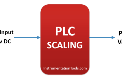
Example 3

Scale PV (Process Value), SP (SetPoint), and CV (Control Variable) for PID (Proportional, Integral, Derivative controller) to consistent or raw units to eliminate scaling errors causing control problems.

Incorrect scaling might lead to inadvertent abuse cases.

Why?

Beneficial for…?Why?
                      Security1. While HMIs typically provide some sort of input validation, a malicious actor can craft or replay modified packets to send arbitrary values to the variables in the PLC which are open to outside influence (open to values passed from an HMI, for example).

2. PLC protocols are typically marketed as “open” protocols and published to the general public, so creating malware that utilizes “open” protocol information can be trivial to develop.

PLC variable mapping can typically occur through traffic analysis during the reconnaissance phases of an attack, thus providing the intruder with the necessary information to craft malicious traffic to the target and thereby manipulate a process with unauthorized tools.

Cross-checking values passed into the PLC before implementing that data into the process ensures valid data ranges and mitigates an invalid value in those memory locations by forcibly setting safe ranges when a value is detected as out-of-bounds during the course of the PLC scan.
Reliability/
Maintenance/

References

Standard/frameworkMapping
MITRE ATT&CK for ICSTactic:  TA010 – Impair Process Control
Technique:  T0836 – Modify Parameter
  ISA 62443-3-3SR 3.5: Input Validation
SR 3.6: Deterministic Output
  ISA 62443-4-2CR 3.5: Input Validation
CR 3.6: Deterministic Output
  ISA 62443-4-1SI-2: Secure coding standards
SVV-1: Security requirements testing
MITRE CWECWE-1320: Improper Protection for Out of Bounds Signal Level Alerts

Source: PLC Security

Don't Miss Our Updates
Be the first to get exclusive content straight to your email.
We promise not to spam you. You can unsubscribe at any time.
Invalid email address
You've successfully subscribed !

Continue Reading

Allen Bradley Bitwise Logical Operations
What is Live Zero in 4-20 mA Current Loop ?
Ladder Logic for Stair-Case wiring using Toggle Switches
Count and Pack Objects from Conveyor using PLC Ladder Logic
PLC Programming for Baking with Auto and Manual Modes
DCS Commissioning Steps
Share This Article
Facebook Whatsapp Whatsapp LinkedIn Copy Link
Share
Leave a Comment

Leave a Reply Cancel reply

Your email address will not be published. Required fields are marked *

Stay Connected

128.3kFollowersLike
69.1kFollowersFollow
208kSubscribersSubscribe
38kFollowersFollow

Categories

Explore More

Control Speed of Induction Motor using Analog Output of PLC
Shutter Door Control using Motor and Limit Switches
PLC Scan Time
What is Resources Tab in the Siemens PLC?
Failsafe Wiring Practices
Create Logic with InTouch Scada using Scripting
1 to 8 Demultiplexer PLC ladder diagram
FactoryTalk View Studio – Import and Export Tutorial

Keep Learning

Open Loop and Closed Loop System Questions

Open Loop and Closed Loop System Questions Answers

Parameters of SRT_DINT instruction

Tia Portal – OB20 Time Delay Interrupt Organization Block

Introduction to SCL Programming in Siemens PLC

Types of Expressions in the SCL Language of the Tia Portal

Door Lock with Delay PLC Exercise Problems

Door Lock with Delay PLC Exercise Problems

Applications of SCADA

Siemens PLC Interview Questions & Answers

Siemens PLC Interview Questions and Answers

Distributed IO for Siemens PLC

How to Configure Distributed IO in a PLC Project?

Lights with Adjustable Timers PLC Programming

Flip-Flop PLC Programming: Lights with Adjustable Timers

Learn More

Skin Type Thermocouple

Skin Type Thermocouple

PLC program pushbutton switches

PLC Permissive for Motor Control

Digital Electronics MCQ

Logic Gates and Networks Objective Questions

Digital Electronics Multiple Choice Questions

D Flip Flop Objective Questions

Use of Comments in SCL Language

Use of Comments in SCL Language

Interview Questions on Battery Testing

Interview Questions on Battery Testing

Site Acceptance Test (SAT) of PLC System

PLC System Site Acceptance Test (SAT)

Automatic Car Door Simulation

Automatic Door Operation PLC Programming and Simulation

Follow US
All rights reserved. Reproduction in whole or in part without written permission is prohibited.
Welcome Back!

Sign in to your account

Username or Email Address
Password

Lost your password?