Inst ToolsInst ToolsInst Tools
  • Courses
  • Videos
  • Q & A
    • Interview
      • Instrumentation
      • Electronics
      • Electrical
      • Practical Questions
    • MCQ
      • Instrumentation MCQ
      • Electrical MCQ
      • Electronics MCQ
      • Control Systems MCQ
      • Analog Electronics MCQ
      • Digital Electronics MCQ
      • Power Electronics MCQ
      • Microprocessor MCQ
      • Multiple Choice Questions
  • EE
    • Electronics
      • Electronics Q & A
      • Electronic Basics
      • Electronic Devices & Circuits
      • Electronics Animation
      • Digital Electronics
    • Electrical
      • Electrical Basics
      • Electrical Q & A
      • Power Electronics
      • Electrical Machines
      • Electrical Animation
      • Power Systems
      • Switchgear & Protection
      • Transmission & Distribution
  • Measure
    • Control Valves
    • Calibration
    • Temperature
    • Pressure
    • Flow
    • Level
    • Analyzers
    • Switches
    • Vibration
    • Solenoid Valve
  • Control
    • PLC Tutorials
    • Control Systems
    • Safety Instrumented System (SIS)
    • Communication
    • Fire & Gas System
  • More
    • Design
    • Tools
    • Animation
    • Basics
    • Formulas
    • Standards
    • TextBooks
    • Common
    • Software
    • Excel Tools
    • Erection & Commissioning
    • Process Fundamentals
    • Videos
    • Books
Search
All rights reserved. Reproduction in whole or in part without written permission is prohibited.
Reading: What is Torque Boosting in Variable Frequency Drive (VFD)?
Share
Notification Show More
Font ResizerAa
Inst ToolsInst Tools
Font ResizerAa
  • Courses
  • PLC Tutorials
  • Control Systems
Search
  • Courses
  • Videos
  • Q & A
    • Interview
    • MCQ
  • EE
    • Electronics
    • Electrical
  • Measure
    • Control Valves
    • Calibration
    • Temperature
    • Pressure
    • Flow
    • Level
    • Analyzers
    • Switches
    • Vibration
    • Solenoid Valve
  • Control
    • PLC Tutorials
    • Control Systems
    • Safety Instrumented System (SIS)
    • Communication
    • Fire & Gas System
  • More
    • Design
    • Tools
    • Animation
    • Basics
    • Formulas
    • Standards
    • TextBooks
    • Common
    • Software
    • Excel Tools
    • Erection & Commissioning
    • Process Fundamentals
    • Videos
    • Books
Follow US
All rights reserved. Reproduction in whole or in part without written permission is prohibited.
Inst Tools > Blog > Electrical Basics > What is Torque Boosting in Variable Frequency Drive (VFD)?

What is Torque Boosting in Variable Frequency Drive (VFD)?

High inertial motor loads can be started by programming the V/f pattern in VFD. This feature is known as Torque Boosting.

Last updated: March 18, 2021 11:48 am
Editorial Staff
Electrical Basics
No Comments
Share
6 Min Read
SHARE

What is Motor Torque?

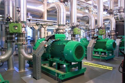
Variable frequency variable voltage (VVVF) or VFD is popularly used for driving the squirrel cage induction motor where speed control is desired to control the process. Substantial power saving can be achieved if the VFD is used for driving the centrifugal fans, blowers, and water pumps.

Contents
What is Motor Torque?How VFD Controls the Speed of Motor?Why is High Starting Torque Required?How VFD can Operate the Motor to supply High Starting Torque?

First, let us understand what the torque of an induction motor is and why starting torque is important for driving the mechanical equipment. When we feed the AC supply to the stator of the induction motor, magnetic flux is set up in the air gap length and the rotor voltage is induced.

The rotor of the motor is short-circuited at the end rings, and thus rotor current starts flowing in the rotor. The torque is produced in the motor because of the interaction of the magnetic flux and the rotor current.

The torque of induction current can be expressed by following mathematical expression.

T = K Φ Ir cos Φ equation (1)

The flux produced in the motor is proportional to the stator supply voltage.

Φ ∝ V

The rotor current is proportional to the slip and the stator supply voltage. At start slip=1,

Therefore,

Ir ∝ V

T = KV2 equation (2)

From the above equation, it is clear that the starting torque of the induction motor is proportional to the square of the stator voltage. 

How VFD Controls the Speed of Motor?

The voltage induced in the stator coil is equal to;

E = 4.44 Φ f T equation (3)

Φ = E / (4.44 f T)

Φ = V / (4.44 f T)

Φ = V / f equation (4)

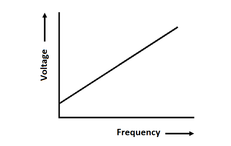
The flux produced in the stator is proportional to the ratio of V/f. The speed of the motor can be expressed by following mathematical expressions.

Ns = (120 f) / P equation (5)

Thus the speed of the motor is proportional to the frequency.

V/f ratio is maintained constant to deliver the rated torque at all the speeds up to the base speed of the motor. If the V/f ratio is maintained constant, the motor operates in the constant torque mode.

Why is High Starting Torque Required?

As per Newton’s laws of motion, the object which is in rest position tries to remain in its rest position if an external force is applied to it. This is called the law of inertia. The same principle applies when a motor drives a mechanical load.

The starting torque demand by the mechanical load depends on the combined moment of inertia of the motor and the driven equipment.

The more inertia, the more the starting torque required. If the motor does not supply the required starting torque then the motor will come to a stall.

How VFD can Operate the Motor to supply High Starting Torque?

VFD generally operates in the constant torque mode by supplying constant volt/Hz to stator of the induction motor.

Torque Boosting in Variable Frequency Drive

The PWM inverter of the VFD increases the voltage and frequency in the same ratio, and thus the torque delivered by the motor remains constant.

For example, if the rated motor voltage and frequency of the motor are 400 volts and 50 Hz, then the V/f ratio is equal to 400/50=8. If the motor runs at half of its rated speed then the VFD output and frequency of the inverter are 200 volts and 50 Hz respectively and the V/f ratio is 200/25=8.

However, some types of loads demand high starting torque. To deliver the high starting torque, the v/f ratio of VFD output is deliberately made more than 8 for a definite time to generate more flux in the airgap.

More flux will lead to more torque than the motor-rated torque. V/f Pattern in the case of starting torque boosting is as given below.

VFD Torque Boosting

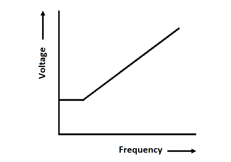
In the above V/f pattern, the voltage and frequency ratio is kept initially more to get more starting torque delivery.

Thus, the high inertial loads can be started by programming the V/f pattern in VFD. This feature of VFD is known as Torque Boosting Feature.

Author: Satyadeo Vyas

If you liked this article, then please subscribe to our YouTube Channel for Instrumentation, Electrical, PLC, and SCADA video tutorials.

You can also follow us on Facebook and Twitter to receive daily updates.

Read Next:

  • Circuit Breaker Interview Questions
  • Variable Frequency Drive Principle
  • AC Motor Speed Control
  • Polarization Index (PI) Test
  • What is Vacuum Circuit Breaker?
Don't Miss Our Updates
Be the first to get exclusive content straight to your email.
We promise not to spam you. You can unsubscribe at any time.
Invalid email address
You've successfully subscribed !

Continue Reading

What is Power Cable? Types of Power Cables
Polarization Index (PI) Test and DA Test
What are HP and LP Switches in HVAC?
What is Switchgear and Electrical Substation?
Difference Between Flame Resistant and Flame Retardant Cables
Top Electrical Engineering Questions & Answers
Share This Article
Facebook Whatsapp Whatsapp LinkedIn Copy Link
Share
Leave a Comment

Leave a Reply Cancel reply

Your email address will not be published. Required fields are marked *

Stay Connected

128.3kFollowersLike
69.1kFollowersFollow
208kSubscribersSubscribe
38kFollowersFollow

Categories

Explore More

Control Two Motors in Sequence after Time Delay – Circuit, Operation
What is a Bus Coupler in Electrical Panel?
Types of Electrical Wiring
What is an Instrument Transformer? – Types, Principle, Advantages
What Happens When a Pump Runs Dry? How to Avoid it?
Electric Motors Efficiency Classes
Working Principle of Overload Relay
Difference Between NEMA and IEC Motors?
Why is HV Testing important in Electrical Panels?
Types of Tripping Protection in MCCB

Keep Learning

Motor Protection Relay

Motor Protection Circuits

Advantages of Star and Delta Systems

Advantages of Star and Delta Systems

What is an Oil Separator in HVAC?

What is an Oil Separator in HVAC?

What is a Core Type Transformer

Difference Between Core and Shell Transformers

Stepper Motor Working Principle Animation

Stepper Motor Working Principle

What is electrical transformer

Basics of Electrical Transformer

What is a Power Transformer

What is a Power Transformer? – Components and Types

Advantages of Valve Regulated Lead Acid (VRLA) Batteries

Advantages of Valve Regulated Lead Acid (VRLA) Batteries

Discover More

Deluge System for Transformer Protection

Deluge System for Transformer Protection Animation

Chromatograph Principle

Basics of Chromatograph Operation

Difference Between Metering CT and Protection CT

Difference Between Metering CT and Protection CT

Convert 2 wire RTD to 4 wire RTD Sensor

How to Convert 2 wire RTD into 3 or 4 wire RTD?

Advantages & Disadvantages of Oil Circuit Breakers

Advantages & Disadvantages of Oil Circuit Breakers

cavitation-control valve trim

What is Control Valve Cavitation ?

Boolean Algebra to PLC Logic

From Boolean Algebra to PLC Logic

mass flowmeters

What is a Thermal Flow Meter?

Follow US
All rights reserved. Reproduction in whole or in part without written permission is prohibited.
Welcome Back!

Sign in to your account

Username or Email Address
Password

Lost your password?