Inst ToolsInst ToolsInst Tools
  • Courses
  • Automation
    • PLC
    • Control System
    • Safety System
    • Communication
    • Fire & Gas System
  • Instrumentation
    • Design
    • Pressure
    • Temperature
    • Flow
    • Level
    • Vibration
    • Analyzer
    • Control Valve
    • Switch
    • Calibration
    • Erection & Commissioning
  • Interview
    • Instrumentation
    • Electrical
    • Electronics
    • Practical
  • Q&A
    • Instrumentation
    • Control System
    • Electrical
    • Electronics
    • Analog Electronics
    • Digital Electronics
    • Power Electronics
    • Microprocessor
  • Request
Search
  • Books
  • Software
  • Projects
  • Process
  • Tools
  • Basics
  • Formula
  • Power Plant
  • Root Cause Analysis
  • Electrical Basics
  • Animation
  • Standards
  • 4-20 mA Course
  • Siemens PLC Course
Reading: Moving Pressure Sensing Level Transmitter from Top to Bottom
Share
Font ResizerAa
Inst ToolsInst Tools
Font ResizerAa
  • Courses
  • Design
  • PLC
  • Interview
  • Control System
Search
  • Courses
  • Automation
    • PLC
    • Control System
    • Safety System
    • Communication
    • Fire & Gas System
  • Instrumentation
    • Design
    • Pressure
    • Temperature
    • Flow
    • Level
    • Vibration
    • Analyzer
    • Control Valve
    • Switch
    • Calibration
    • Erection & Commissioning
  • Interview
    • Instrumentation
    • Electrical
    • Electronics
    • Practical
  • Q&A
    • Instrumentation
    • Control System
    • Electrical
    • Electronics
    • Analog Electronics
    • Digital Electronics
    • Power Electronics
    • Microprocessor
  • Request
Follow US
All rights reserved. Reproduction in whole or in part without written permission is prohibited.
Inst Tools > Blog > Practical Questions > Moving Pressure Sensing Level Transmitter from Top to Bottom

Moving Pressure Sensing Level Transmitter from Top to Bottom

Calculate the new calibration points after moving the pressure sensing level transmitter from top to bottom of a water tank.

Last updated: November 10, 2020 3:47 pm
Editorial Staff
Practical Questions
No Comments
Share
3 Min Read
SHARE

A water storage vessel is elevated by a tower structure, to provide a natural source of water pressure to all points of use below:

Pressure Sensing Level Transmitter

Moving the Pressure Sensing Level Transmitter from Top to Bottom

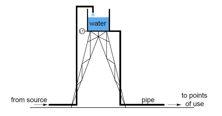
A pressure-sensing level transmitter is presently located at the base of the vessel, at the top of the tower structure, to measure water level inside the vessel.

It has a calibrated range of 0 to 10 feet (0 to 120 inches W.C.). Unfortunately, the water inside the transmitter sometimes freezes in the winter months, preventing operation of the level measurement system.

The water inside the storage vessel and the large pipes never freezes, because there is enough circulation as a result of water usage to raise the temperature and prevent ice crystals from forming.

It is decided to move the transmitter to ground level, at the base of the tower, so that it may be located inside a small, heated shelter where it will never freeze.

By connecting the transmitter directly to the large water pipe carrying water from the vessel to the points of use, the hydrostatic pressure will still be measurable at this point:

Pressure-sensing level transmitter

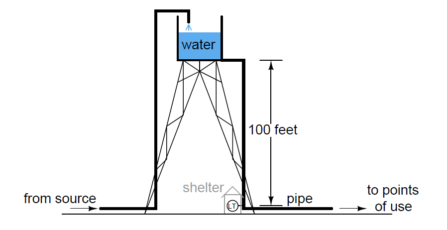
Calculate the new calibration points (lower and upper range-values) for the transmitter in its new location.

Also calculate the water level in the vessel when the transmitter output is 13.7 mA, and the amount of hydrostatic pressure at that point in units of PSI.

Finally, identify whether the transmitter move resulted in a shift of its zero, a shift in its span, or both.

Answer:

Lower range-values: 100 feet W.C. input (1200 inches W.C.) = 4 mA output

Upper range-values: 110 feet W.C. input (1320 inches W.C.) = 20 mA output

Water level in vessel at 13.7 mA = 6.0625 feet ; applied pressure = 45.98 PSI

Share your answers & explanation with us through the below comments section.

Read Next:

  • Types of Tank Gauging
  • Level Transmitter Errors
  • Sump Tank Level Transmitter
  • Magnetostrictive Level Sensor
  • Cat and Mouse Level Gauge

Credits: Tony R. Kuphaldt

Don't Miss Our Updates
Be the first to get exclusive content straight to your email.
We promise not to spam you. You can unsubscribe at any time.
Invalid email address
You've successfully subscribed !

Continue Reading

Programmable Logic Controller (PLC) Questions and Answers – 10
Calculate the 0%, 50%, and 100% Calibration Points
Solenoid-controlled Valve Problem
How Much Pressure Indicated by Micromanometer?
Determine Resistance value of Resistors
Calculate Incident Power in Radar Level Measurement
Share This Article
Facebook Whatsapp Whatsapp LinkedIn Copy Link
Share
Leave a Comment

Leave a Reply Cancel reply

Your email address will not be published. Required fields are marked *

Stay Connected

128.3kFollowersLike
69.1kFollowersFollow
210kSubscribersSubscribe
38kFollowersFollow

Categories

Explore More

Questions on DP Transmitter Wet Leg Compensating Impulse Line
Practical Process Control System Questions & Answers – 5
Baffle Nozzle Question
Baffle Nozzle Assembly Sensitive Mechanism
How to Draw a Schematic Diagram ?
Which Tube has most Hydrostatic Pressure?
Something is Wrong with Strain Gauge Bridge Circuit
Identify Two Pressure Switches Logic

Keep Learning

PLC program to control a water pump

PLC Program to Control a Water Pump

steam heat exchanger

Practical Process Control System Questions & Answers – 9

Loop Diagram

PT Loop Diagram Faults

What Effect on Hydrostatic Level Transmitter if Liquid Density Changes?

What Effect on Hydrostatic Level Transmitter if Liquid Density Changes?

three-phase motor control circuits

How Overload Heaters used to Automatically Shut the Motor OFF ?

Level Loop Troubleshooting

Identify Faults in PID Control Loop

Pneumatic Transmitter

Questions on Pneumatic Transmitter and Repeater

10 Questions on Reforming Furnace Control System

10 Questions on Reforming Furnace Control System

Learn More

Multi Way Switches using PLC

Making Multi Way Switches using PLC

Why Three-phase Voltage is 440 Volts

Why Three-phase Voltage is 440 Volts?

How to Troubleshoot Control Valve - Problems and Solutions

How to Troubleshoot Control Valve? – Problems and Solutions

Bellows-Type Steam Trap

Bellows Steam Trap

Metal Foil Strain Gauge Principle

Metal Foil Strain Gauge Principle

Digital Electronics Objective Questions

Digital Electronics Objective Questions – Set 1

Membrane Bioreactor in Water Treatment - MBR Process

Membrane Bioreactor in Water Treatment – MBR Process

Normally closed input actuator as stop button.

Normally-Closed Contacts for Stop Buttons

Menu

  • About
  • Privacy Policy
  • Copyright

Quick Links

  • Learn PLC
  • Helping Hand
  • Part Time Job

YouTube Subscribe

Follow US
All rights reserved. Reproduction in whole or in part without written permission is prohibited.
Welcome Back!

Sign in to your account

Username or Email Address
Password

Lost your password?